Section 3: Test and Calibration
frequency to make the display amplitude at base standard frequency 80% of the checked spare on
the screen (usually 6 grids), and record the peak-peak value, increase the output frequency of
signal generator until the peak-peak value to 0.707 HO that the frequency is the actual value of
bandwidth.
C. Repeat step B and test bandwidth for every channel.
3.3.7 Transient response inspection
A. As shown by Figure 5 connected:
Tested oscilloscope
Oscilloscope calibration
Output faster edge
CH1-BNC
Q" connection
Figure 5: Connection of transient response inspection
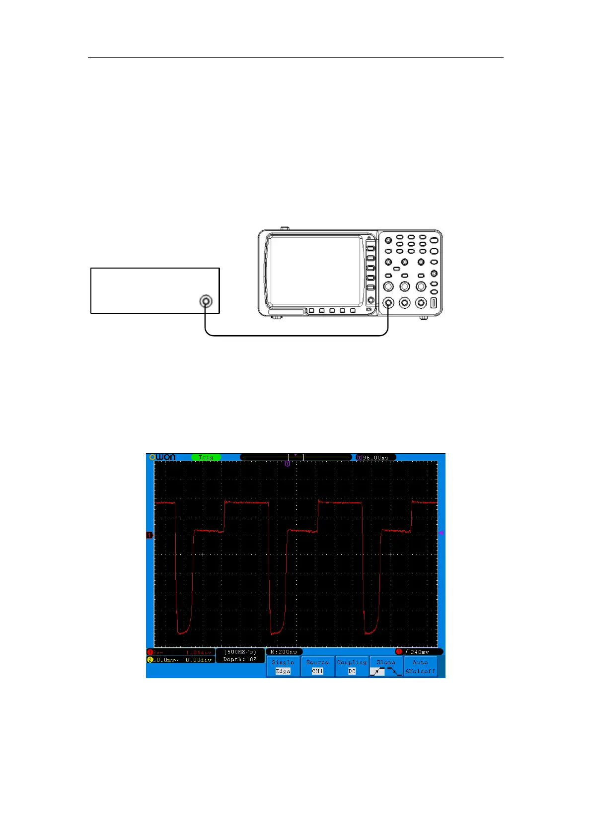
B. Set the period of the faster edge pulse as 1uS, adjust its output amplitude to make the waveform
take up about 80% spare of the checked working amplitude on the screen (usually 6 grids), and
regulate the zero point position to make the 0% of amplitude A and the 100% of amplitude A align
with the level of calibration line respectively, then also adjust the time base and trigger level to
make the mid-point waveform on the center screen. Shown as Figure 6:
Figure 6: Waveform of transient response inspection
Measure the time t from 10% of amplitude to 90% by cursor time that is rise time and measure the
rise-up range B by cursor voltage and get the rise-up value as follows:
Rise-up value S/B%A$100%
C. Repeat step B and check the other channel.
13
 Loading...