Section 3: Test and Calibration
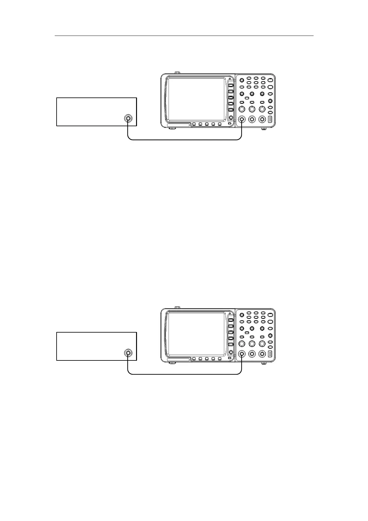
Tested oscilloscope
LCR tester
CH1-BNC
Q" connection
Figure 8: Connection of input impedance inspection
B. The inspected oscilloscope comes into work and record resistance and capacitance of the input
end and measure every voltage division separately.
C. Repeat step B and test the other channel.
3.3.11 Drift test
Turn the voltage of CH1 and CH2 at 5mV, time base at 1mS; record the drift value of zero
position at the set time.
3.3.12 Noise testing
Turn the voltage of CH1 and CH2 at 5mV, time base at 1mS; record the max displayed amplitude,
which is the open-circuit noise.
3.3.13 Maximum input voltage testing
A. As shown by Figure 9 connected:
Tested oscilloscope
Voltage Source
CH1-BNC
Q" connection
Figure 9: Connection of maximum input voltage testing
B. Turn on the unit, set the input coupling as DC and zero position at the center. Then adjust the
output voltage to be in accordance with the set value in product standard. Input voltage and last for
one minute and then cut off input voltage, the unit should work normally.
3.3.14 Average function testing
A. As shown by Figure 3 connected.
B. Make the calibration to output 30mV of the square wave and voltage division at 5mV, and the
sampling is the average sampling with different average numbers to observe the different
15
 Loading...