Prepare the location
Version 1.3, 2021-12-14 21
1
2
3
4
5
1 Electrical compartment - Isolator switch
- Horizontal entry
- UV-C water sterilizer (optional)
2 Duct - IntrCooll® Std.: 600 mm x 600 mm
- IntrCooll® Plus: 900 mm x 900 mm
- 20 mm - 30 mm ange
- Fasten with screws (do not screw in the red zone!)
3 Water supply
compartment
- ¾" male connection
- Always use SS ex hose with swivel
4 Overow - IntrCooll® Std.: 1" male connection
-
IntrCooll® Plus: 1
1
/
4
"male connection
5 Pump compartment
6 Drain valve - 1½" male connection
7 50 Hz - 60 Hz by-pass
compartment
- Standard the 50 Hz cap is mounted
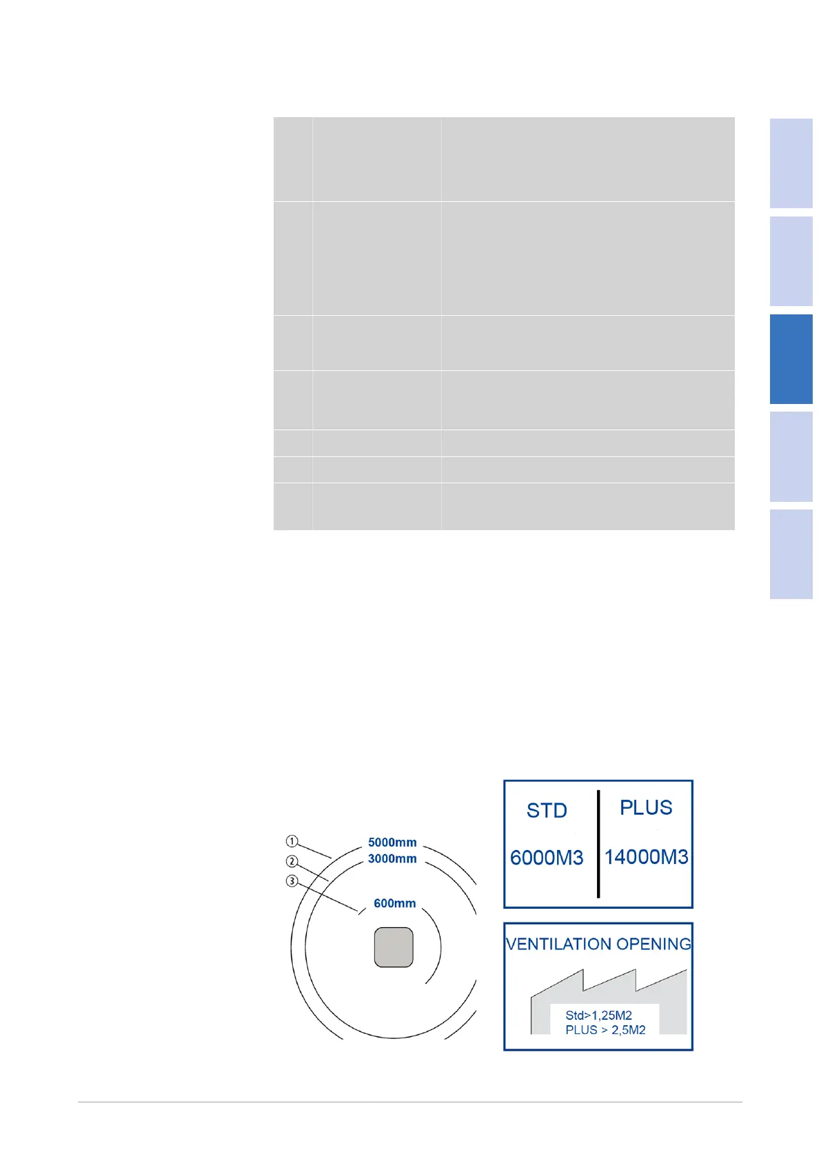
3.1.2.3 Free space around equipment
The IntrCooll® needs sucient space around the unit to ensure that it functions
correct and to make servicing possible.
The recommended minimum free space around the IntrCooll® is 1000 mm for at
least three sides of the unit and at least 600 mm of free space at the fourth side.
If the unit is placed higher than 1.5 m above the roof or oor a service platform
must be available for servicing purposes.
Obstacle minimum distance