Do you have a question about the Ozito SCMS-1621MS and is the answer not in the manual?
Explains the 36-month replacement warranty terms and exclusions.
Step-by-step guide for assembling the mitre saw components.
How to adjust material supports for workpiece stability.
Guidance on setting the desired mitre angle for cuts.
Instructions for tilting the cutting head to the desired bevel angle.
Details on using the trenching feature for depth-controlled cuts.
How to perform a straight cut with the mitre saw.
Guidance on making mitre cuts at various angles.
Instructions for performing bevel cuts on the left side.
How to execute combined mitre and bevel cuts.
How to activate and use the laser guide for accurate alignment.
Procedure for safely starting and stopping the mitre saw motor.
Step-by-step guide for making cuts with the mitre saw.
How to use the sliding feature for wider workpieces.
Explains the 36-month replacement warranty for the stand.
Step-by-step guide for assembling the mitre saw stand.
Steps for securing the mitre saw to the stand using bolts.
How to adjust extension arms and roller height on the stand.
Guidance on using material support shelves for repetitive cuts.
How to clean dirt and dust from the mitre saw stand.
Guidance on folding and storing the mitre saw stand.
This document provides comprehensive instructions for the Ozito SCMS-1621MS Sliding Compound Mitre Saw and its accompanying Mitre Saw Stand. The manual covers the function, usage, and maintenance of both devices, ensuring safe and efficient operation.
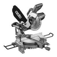
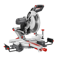
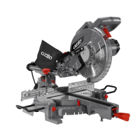
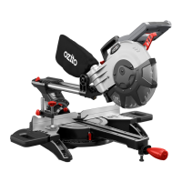
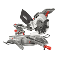
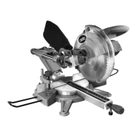
Function Description The Ozito SCMS-1621MS is a powerful 1600W sliding compound mitre saw designed for precise cutting of various materials, primarily wood. It is capable of performing straight cuts, mitre cuts, bevel cuts (left), and compound mitre cuts. The sliding mechanism allows for cutting wider workpieces, while the adjustable mitre and bevel angles provide versatility for different cutting requirements. A laser guide is integrated to assist with aligning workpieces for more accurate cuts. The saw is equipped with a blade guard for safety and a dust bag for collection of sawdust, promoting a cleaner work environment.
Usage Features The mitre saw offers several features to enhance usability and precision. For mitre angle adjustments, the mitre lock can be flipped upwards to unlock the mitre table. Holding down the release button allows the user to rotate the table to the desired mitre angle. The table includes positive click stops at common angles (-45°, -30°, -22.5°, -15°, 0°, 15°, 22.5°, 30°, and 45°) for quick and accurate setting. Once the angle is set, releasing the button and pressing down the mitre lock secures the table.
For bevel angle adjustments, the bevel lock needs to be loosened, allowing the cutting head to be tilted to the desired bevel angle. It is crucial to fully tighten the bevel lock before making a cut to prevent unexpected movement and serious personal injury. When performing bevel cuts, the fence screw should be loosened, and the upper fence slid out of the way of the saw blade to ensure no part of the tool contacts the fence during cutting. The fence screw must then be retightened.
The saw also supports trenching, which involves controlling the depth of cut. Before using this function for the first time, the trenching stop needs to be moved into position by loosening its screw and sliding the stop plate towards the front of the saw, then retightening. The lock nut is loosened, and the cutting depth screw rotated to set the desired trenching depth. The cutting head is then lowered to check that the blade stops at the correct position. Once the depth is confirmed, the lock nut is retightened. It is recommended to test the setting on a scrap piece of wood first.
Material clamping is essential for securing workpieces. The material clamp can be mounted on either side of the tool, with the right side being appropriate for bevel cuts. The metal pole is inserted into a slot and secured with a pole screw. The workpiece is placed flat on the mitre table, with one edge against the rear fence. If the workpiece is warped, the concave side should face the rear fence. The clamp screw is then tightened onto the workpiece.
For operating the saw, the workpiece must be securely clamped down. The saw is started by pressing and holding the safety lock-off button, then squeezing the on/off trigger. The lock-off button can be released once the saw starts. It is important to allow the blade to reach full speed before making a cut to prevent lock-up or blunting. For narrow pieces, the sliding action may not be necessary, and the slide locking knob should be tight. For wider workpieces (over 100mm), the slide lock is loosened to allow the cutting head to slide freely. When cutting, the head is lowered steadily until it cuts through the workpiece. If sliding action is used, the cutting head is lowered fully against the mitre table and then pushed backward. The blade guard automatically retracts during lowering. After the cut, the on/off trigger is released, and the blade allowed to stop completely before raising the cutting head back to its original position, applying slight counter-pressure against the springs to prevent bouncing.
The laser guide is activated by pressing the laser button and switched off by pressing it to the '0' position. It should be switched off when not in use.
Maintenance Features Regular maintenance is crucial for the longevity and safe operation of the mitre saw. Cleaning the appliance immediately after use is recommended. Safety devices should be kept free of dirt and dust, and the equipment wiped with a damp cloth and soft soap. Cleaning agents or solvents should be avoided as they can damage plastic parts. Water should not enter the interior of the appliance.
For storage and transport, the mains plug should be pulled, the tool switched off, and secured to prevent unauthorised starting. The tool should be stored in a dry location inaccessible to unauthorised persons. For transport, the cutting head should be lowered, and the lock-down pin pushed in to secure it. The slide lock should be tightened. The saw must never be used with the lock-down pin engaged.
Carbon brushes are wearing components that need periodic inspection. If the saw sparks or stops, the carbon brushes may be worn out and should be replaced by an electrician or power tool repairer. Both carbon brushes must be replaced at the same time. Continuing to use the saw with worn brushes can cause permanent damage.
If the supply cord is damaged, it must be replaced by a certified electrician to avoid a safety hazard.
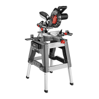
Function Description The Ozito Mitre Saw Stand is a robust and portable stand designed to support mitre saws, facilitating stable and accurate cutting. It features extension arms with rollers and material support shelves, allowing for the support of long workpieces and repetitive cuts. The stand is foldable for convenient storage and transport.
Usage Features The stand is designed for easy assembly and unfolding. To unfold, the stand is laid on the floor with folded legs facing up. The leg locking buttons are depressed, and the two upper legs unfolded until the buttons click into place. This process is repeated for the other two legs. The stand is then lifted into an upright position, ensuring it is stable and all leg locking buttons are engaged.
For folding the stand, it is turned upside down with the legs sticking up. The leg locking buttons on the lower pair of legs are depressed, and the legs folded in. This is repeated for the other pair of legs. It is important that one pair of legs folds in first for the stand to fold flat.
Attaching the extension arms involves sliding them into the frame. The locking pin on the extension arms should face inwards towards the centreline of the stand. The pin needs to be depressed twice (once when it reaches the frame and again when it pops through the locating hole). The extension arm is slid into the frame until the desired length is reached. A fastening knob is then inserted into the hole on the frame and turned clockwise to secure the arm. A roller arm is inserted into the collar on the extension arm, ensuring the material support shelf faces inwards. A fastening knob is inserted into the bracket and turned clockwise to tighten the roller arm. This process is repeated for the opposite extension arm.
Attaching the mitre saw to the stand requires adjusting the mounting bars to roughly the width of the mitre saw base. The mitre saw is placed on the mounting bars, aligning the holes in the saw base with the slots on the bars. A bolt is fed through the bottom of the mounting bar and the saw base. A washer and a spring washer are slid onto the bolt, and it is fastened with a hex nut. This is repeated for the other three holes. It is crucial to ensure all screws and nuts are tightened correctly and securely before operation.
Adjusting the extension arms involves turning the fastening knob on the frame counter-clockwise to loosen it, then pulling the arm out to the desired length. The maximum extension is reached when the arm locking pin clicks into place. To shorten, the pin is depressed, and the arm pushed back. The fastening knob is then turned clockwise to secure the arm.
Adjusting the roller height is done by turning the fastening knob on the collar of the extension arm counter-clockwise to loosen it, then raising or lowering the roller to the desired height. The knob is then turned clockwise to secure the roller.
Using the material support shelves involves adjusting the height of the roller arm so that its lip is in line with the work surface of the mitre saw. The extension arms are adjusted to the desired cutting length. The end of the workpiece is placed against the material support shelf to commence the cut.
Maintenance Features For appliance care, the Mitre Saw Stand should be wiped clean of dirt and dust regularly.
For storage, the stand can be easily folded. The mitre saw should be detached before folding. The leg assembly instructions are followed in reverse to fold up the stand. When transporting the stand in a vehicle, it should always be tied down to prevent movement and damage.
| Type | Sliding Compound Mitre Saw |
|---|---|
| Motor Power | 1600W |
| Blade Diameter | 210mm |
| No Load Speed | 5000 RPM |
| Bore Size | 30mm |
| Max Cutting Capacity (at 90 degrees) | 65 x 310mm |
| Max Cutting Capacity (at 45 degrees) | 65 x 210mm |
| Bevel Capacity | 45° Left |
| Mitre Range | 0 - 45 degrees left and right |