© 2024 Stinger Solutions
Pacific Accessory Corporation
Page 2
Rev: 1
Date:09242024
Advanced Amplier Interface
for Select Toyota Applications
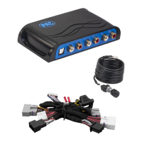
AP4-TY14
Installation
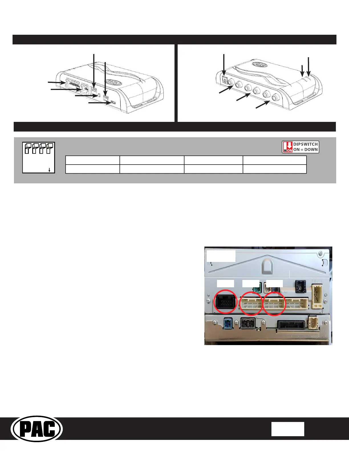
1. Remove the factory radio.
2. Disconnect the 28-pin, 30-pin and 10-pin connectors from the radio.
3. Ensure that you only remove the 28-pin and 30-pin connector that is
closest to the 10-pin connector, the correct 28-pin connector will be
either gray or white depending on the vehicle. There is another 28-
pin connector on the radio that will not be used. See Figure 1.
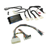
4. Connect the AmpPRO harnesses to the vehicle harnesses.
5. Connect the AmpPRO harnesses to the factory radio.
6. Set any feature DIP switches that apply to your install.
a. DIP switch 1 is used for two channel mode. In this mode, both
the TOSLINK and front RCA outputs (1 and 2) become non-
fading outputs and makes all chimes play through only the
TOSLINK and front RCA outputs (1 and 2).
b. Set DIP switch 2 on (down) to lower the RCA output voltage to
4v. Leave DIP switch 2 off (up) to keep the RCA output voltage at
5v. See troubleshooting section on Page 6 for more details.
c. DIP switch 3 is not used and should remain off (up).
d. DIP switch 4 is not used and should remain off (up).
6. If you are using the APA-TOS1 (sold separately) refer to the
instructions included with that product for its installation.
7. Connect the AmpPRO harness to the module.
8. Connect the level control knob to the module and install in an
accessible location.
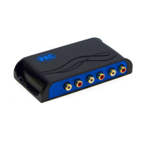
9. Connect the signal cables and remote input from the aftermarket
amplier.
10. The Yellow / Black "SOS Mute" wire will be used in conjunction with
the Safety Connect (SOS) Retention. See Page 3 for more details.
Two Channel Mode 5v / 4v Preout Not Used Not Used
1 2 3 4
Set DIP switches to the ON position to activate the corresponding features.
Set DIP switches to the OFF position for any features that are not desired.
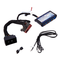
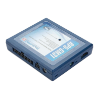
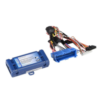
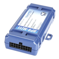
Module Layout
LED 1
Interface Connector 1
Expansion Port
TOSLINK Output
(APA-TOS1 sold separately)
Programming Button
Feature Select
DIP switches
Front Output
Ch. 1(L) and 2(R)
Non-Fading Level Control
Knob Connection
USB Connection
Rear Output
Ch. 3(L) and 4(R)
Non-Fading Output
Ch. 5(L) and 6(R)
LED 2