System Operations Manual
www.paceworldwide.com
Page 10 of 50
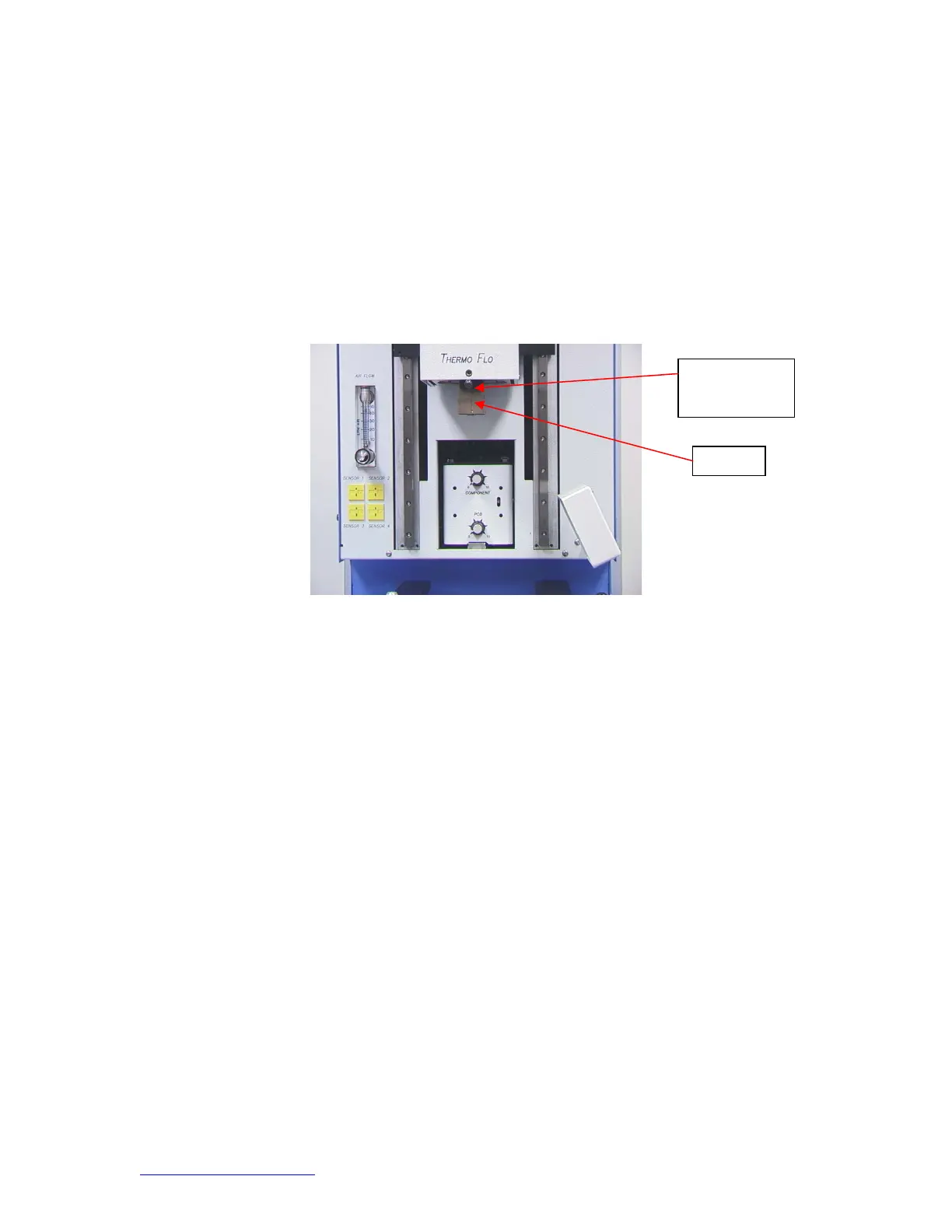
Figure 3a
d. Inserting/changing nozzle. (Figure 3b)
i. Insert proper size nozzle. The OD of the nozzle should be 3 mm larger
than the outside of the component. If the proper nozzle size cannot fit
onto the PCB due to adjacent components being to close, use a smaller
nozzle or keep the nozzle approximately 1mm above the part. Align the
nozzle under the square hole in the reflow head. The nozzle snaps into
place. The nozzle can be positioned with the front surface parallel to the
PCB or at a diagonal by moving the lever on the nozzle housing. To
rotate the nozzle, first loosen the retention screw in front of the housing.
Figure 3b
ozzle
Lever to rotate
nozzle