System Operations Manual
www.paceworldwide.com
Page 16 of 50
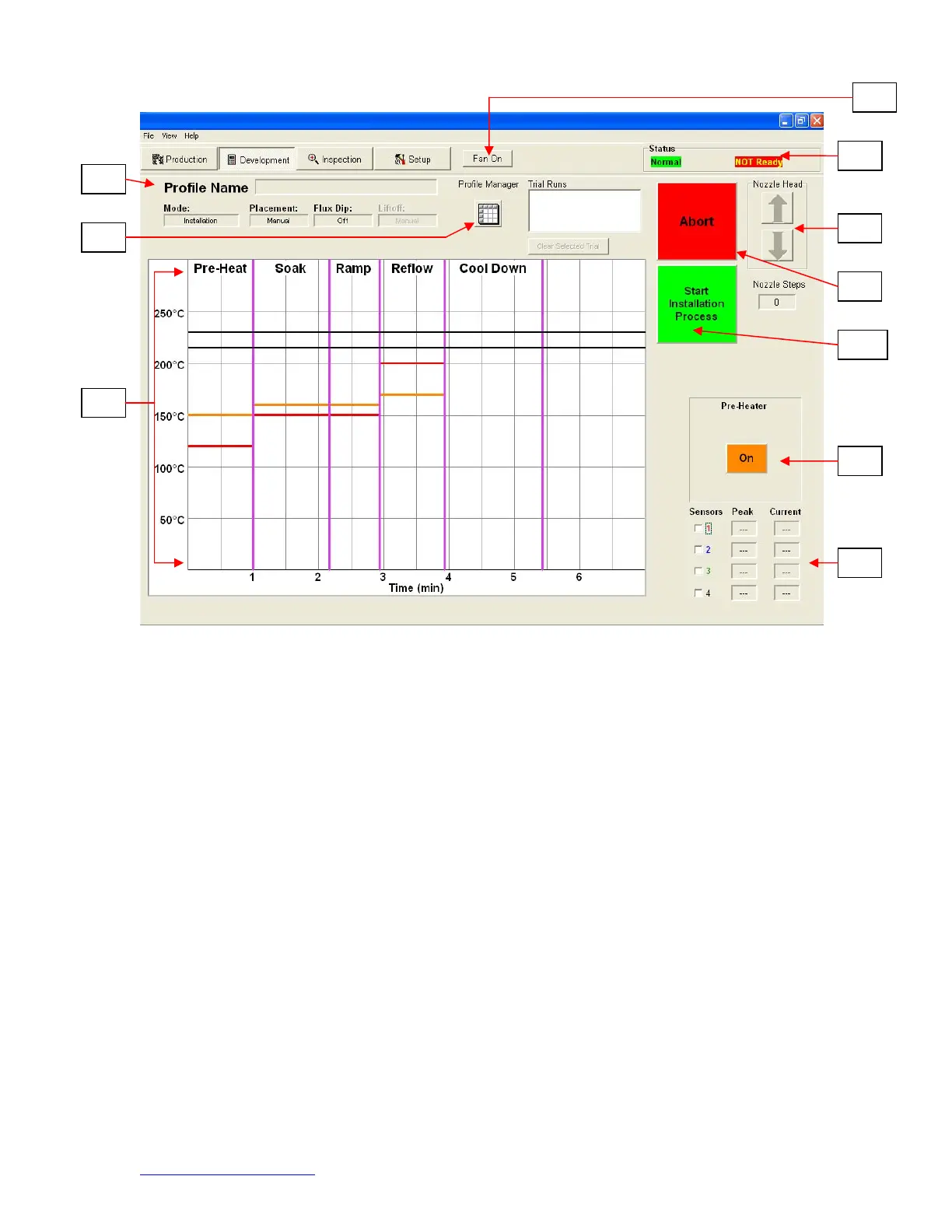
Figure 7a
i. Profile Name. Indicates currently selected profile.
ii. Profile Manager. Temperature and time setting entered by the developer can
be viewed managed here (Figure 7a).
iii. Graph. A saved graph and, if thermocouples are used, an active trace graph
are viewed here.
iv. Fan On/Off Selector. Manual on/off switch for the cooling fan.
v. Status Bar.
1. System status – shows if system is “normal,” in “setback” or “shutdown.”
2. Heater status – Shows “ready” if bottom heater is in range. Shows “not
ready” if bottom heater is not in range. The software will not continue until
it is in “ready” status.
vi. Nozzle Step Indicator. Indicates how many steps the nozzle will lower to
properly position itself for operation.
vii. Abort Button. Click at any time to abort the process and return to the
beginning.
viii. Sequencing Button. Click here to proceed to next step in the operation.
ix. Pre-Heater indicator. Indicates if pre-heater is on or off.
x. Sensor indicators. Real-time sensor readings can be viewed here if
thermocouples are used.
ix
d. Profile Development Screen (Figure 7)