System Operations Manual
www.paceworldwide.com
Page 25 of 50
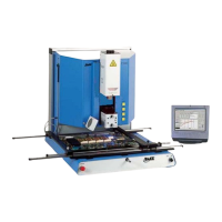
v. Align PCB so red laser sighting light is roughly centered on BGA.
(Figure 10)
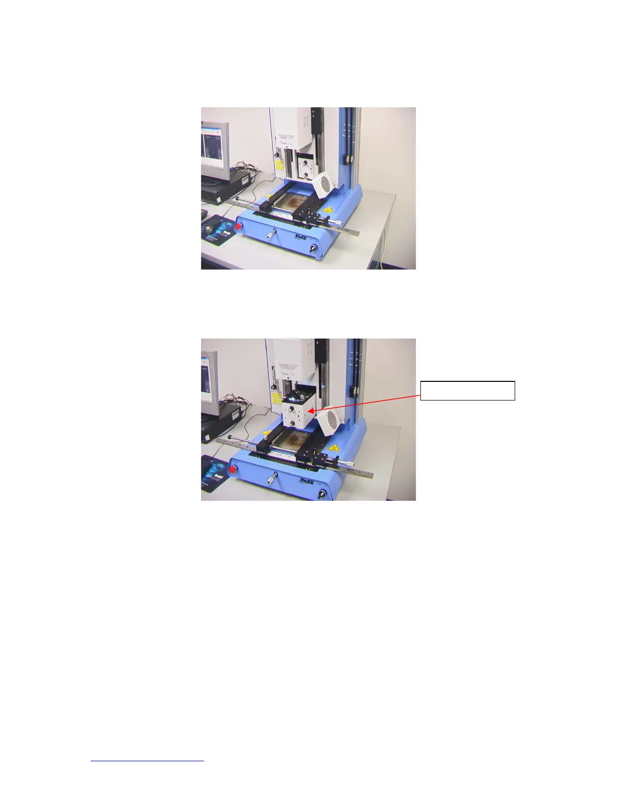
Figure 11
vi. Mouse click on green button, “Pickup.”
vii. Mouse click “OK” when message prompt (Please load PCB into board
holder) appears.
Figure 11
viii. Mouse click on green button, “Focus button.”
ix. Align image of board with image of component and click the “place”
button.
x. Adjust focus and zoom with up and down arrows on keyboard or by
moving slide on screen.
xi. Image in the window should be aligned like figure 12.
Camera Housin