System Operations Manual
www.paceworldwide.com
Page 28 of 50
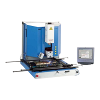
Figure 17
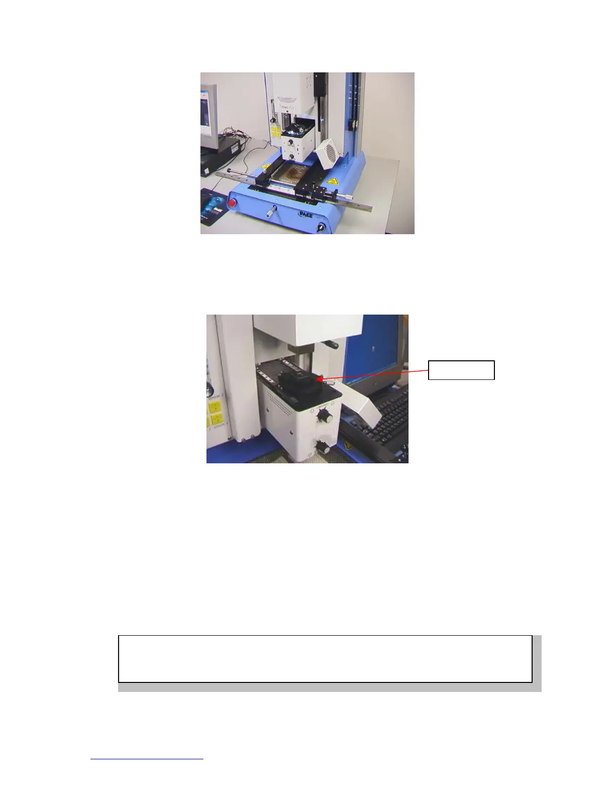
viii. Place the component in the mounting plate on top of the camera
housing. (Figure 18) The component needs to be oriented the same
as the nozzle.
Figure 18
ix. Mouse click on the green button. The BGA workstation will pick up
component.
x. Slide component mount away from the top of the camera housing.
xi. If Flux Dip option was selected, place the flux dip assembly on top of
the camera housing. (Figure 19) Mouse click to dip, then remove flux
dip assembly.
xii. Mouse click on the green button to pick component from holder.
xiii. Slide component nest / flux tray support back out of the way so optics
are unobstructed.
xiv. Mouse click on the green button again to switch to the alignment
screen and lower component to focus point. (Figure 5)
Com
onen
WARNING: TF 1700 USERS ONLY
When using the optional 65mm x 65mm component nest, (P/N 6000-0285) Nest must be removed
from camera housing before camera is allowed to retract. ALLOWING OPTIONAL NEST TO