System Operations Manual
www.paceworldwide.com
Page 29 of 50
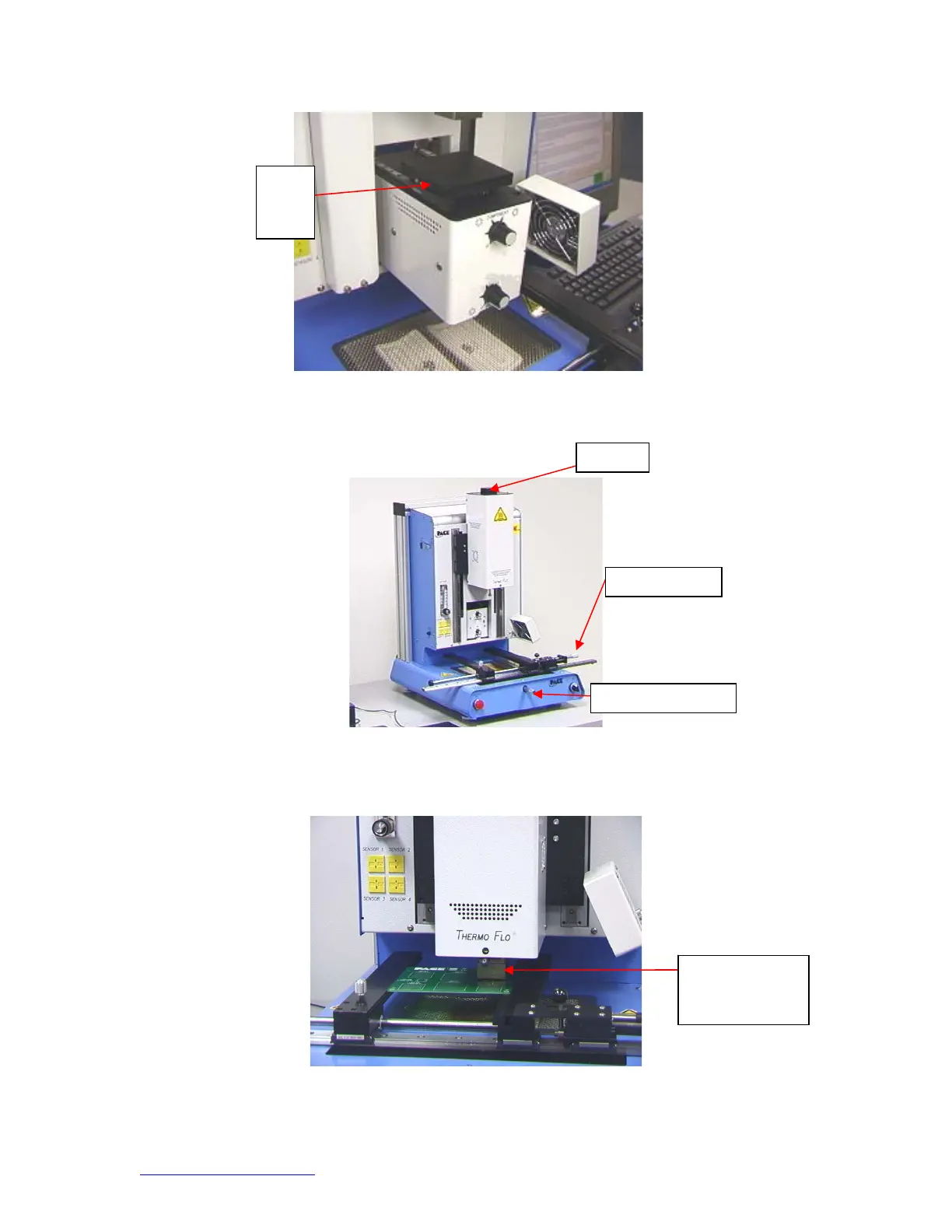
Figure 19
xv. Zoom in and align using the X, Y, and theta axis adjustments until the
component is aligned. (Figures 5 & 20)
Figure 20
xvi. Mouse click on the green button, “Place” to lower the component.
(Figure 21)
Figure 21
xvii. Mouse click on the green button again, “Start.”
Nozzle on board
ready to start
heating
Theta
Left and Ri
h
Fo
ward and Bac
Flux
Dip
Tray