44
Route the two wires to the connector on
the alternator and cut to length. Strip ¼” of
insulation from both wires.
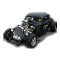
The factory 4 pin alternator connector from
a factory GM harness or a CS-130 pigtail
purchased from Painless, part # 30707
(see photo), will need to be used. Due to a
lack of usage by most customers it is not
included with this Painless chassis
harness.
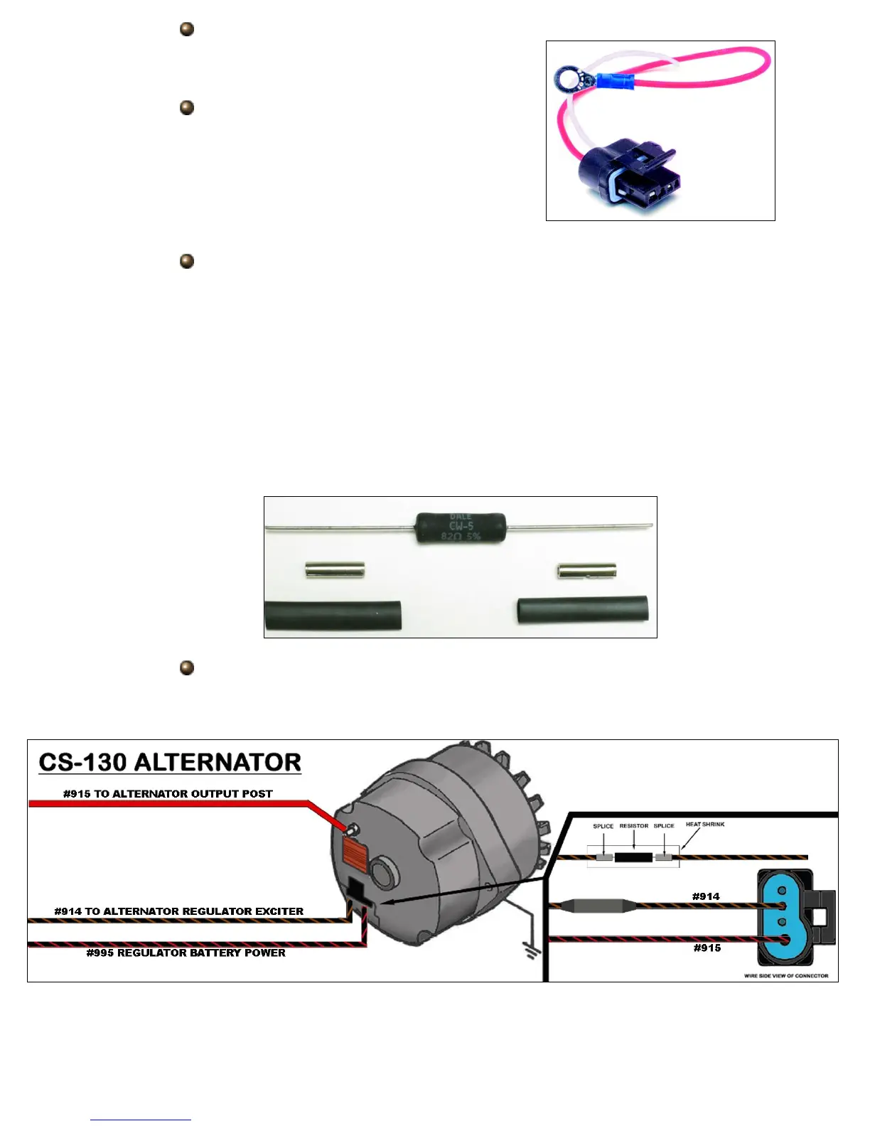
The CS-130 alternator requires a resistance on the #914 wire. Without this
resistance the regulator on the alternator will burn up. A resistor, splices,
and heat shrink, seen below, have been provided in the “ALTERNATOR”
bag kit. The resistor* will simply need to be installed inline on the #914
wire as shown in the diagram on the next page.
*In factory applications where this alternator was used this resistance was created
through a charge indicator light. For those with an instrument panel with a charge
indicator light, the resistor will not be needed. However the #914 wire will need to be
routed to one side of the charge indicator light and the other side of the light will then
route out to the alternator. A charge indicator light was further explained on page 41.
Using two of the splices and heat shrink provided in the “ALTERNATOR”
bag kit, splice the CS-130 pigtail to the #914 and #995 wires according to
the diagram below.