4
Sensor Technology
28
Subject to change without notice
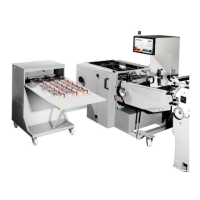
4.4 Sensor B 5
Sensor Position/Name Adjustment
B5 Batch pressure The plunger must be adjusted using the grub screw so
that the distance A between the plunger and the pressing
bar is 1-2mm. N.B. Set the adjusting frame to its largest
format and check if measurement A is correct with
pressing bar both retracted and extended.
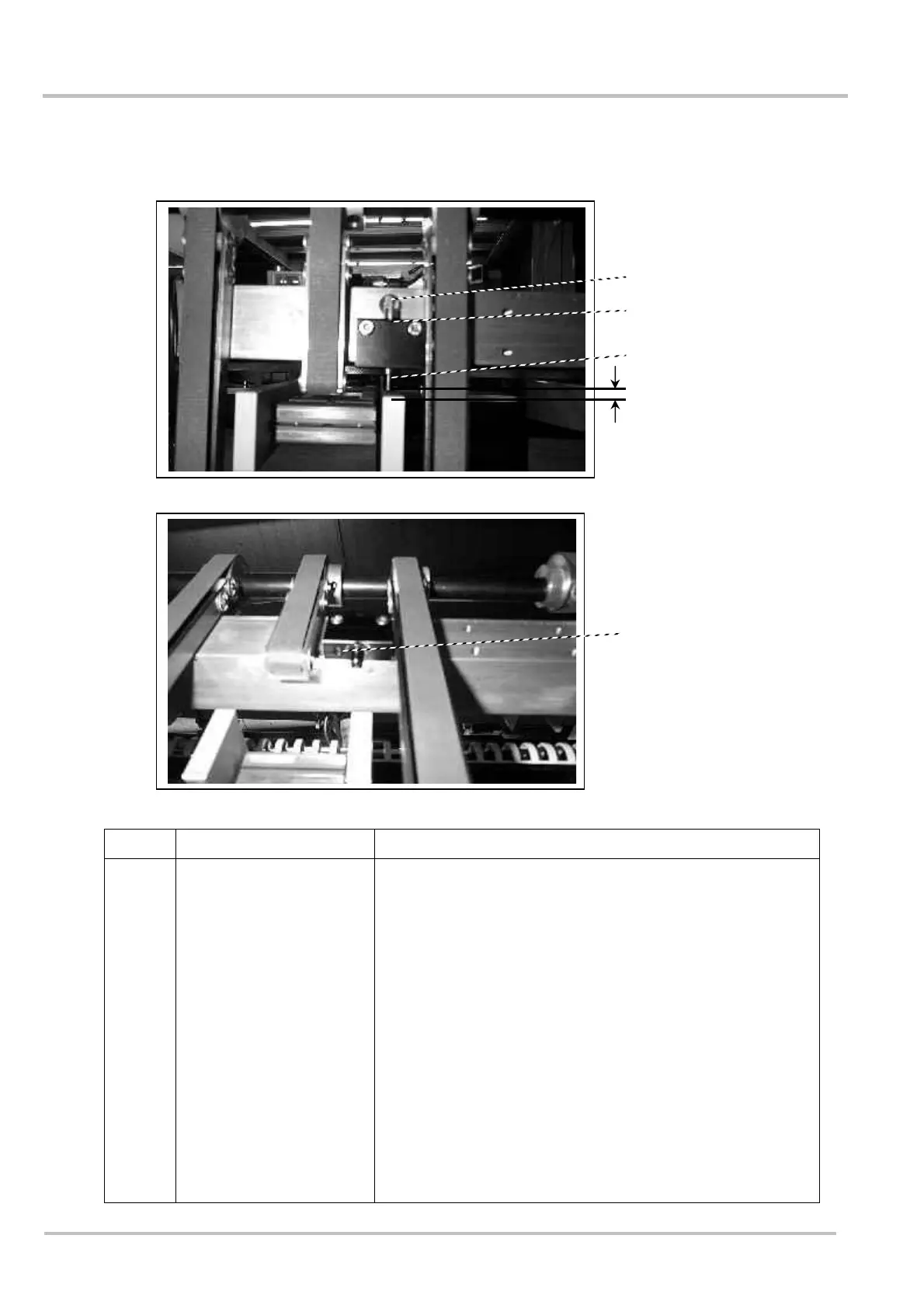
Start the packaging process with one bundle in the
middle shaft and stop it using the stop button as the
bundle is being pressed.
Call up sensor B5 via code 203. Keep turning adjusting
screw (cylinder head cap screw) clockwise until the
display shows 0.
Unscrew the cylinder head cap screw anti-clockwise until
1 appears on the display. Now unscrew the cylinder head
cap screw a further full turn anti-clockwise.
Grub screw
Plunger
Adjustment screw
B5
A