•
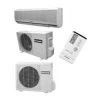
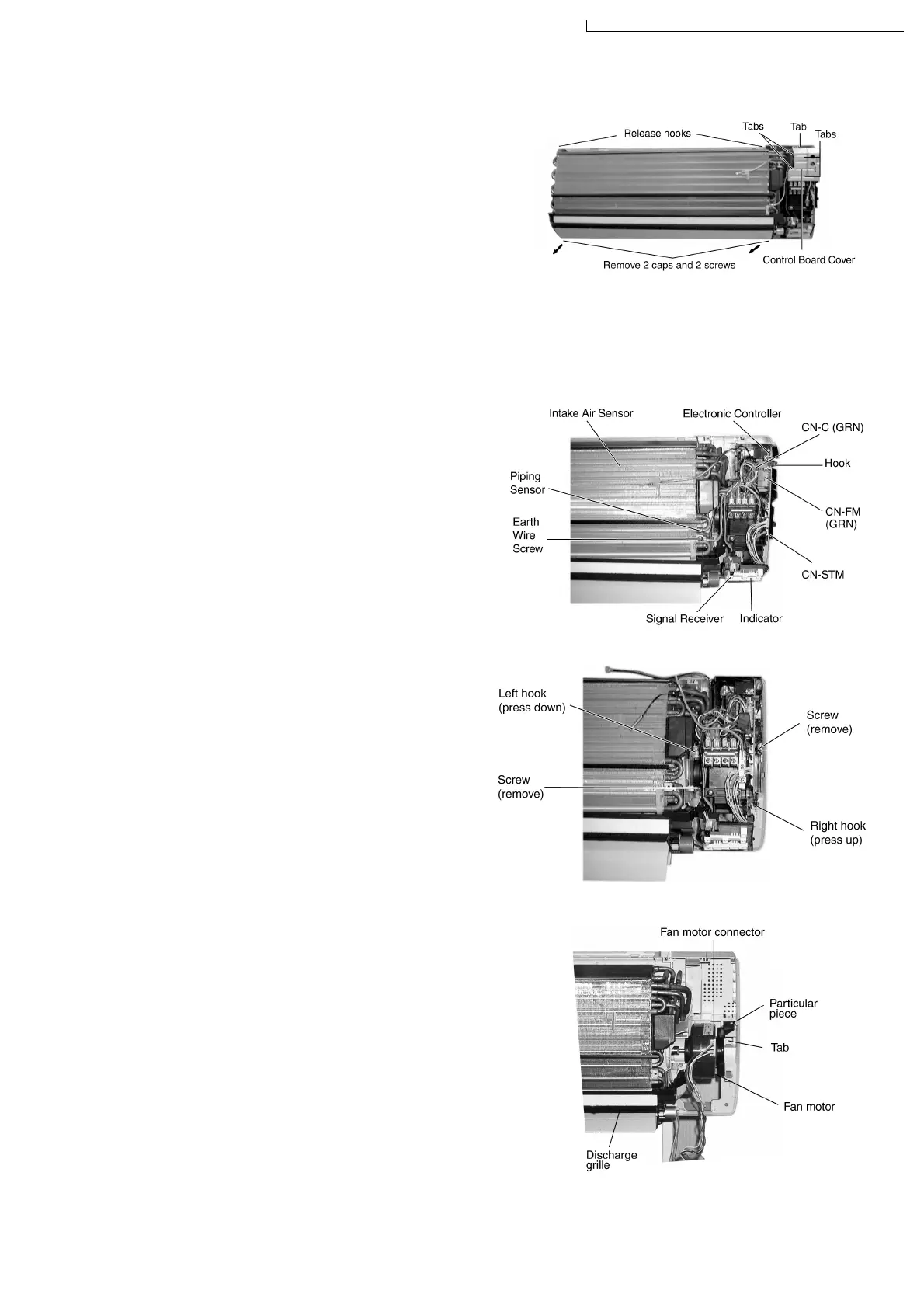
Inspection points for the Indoor Electronic Controller
1. The Electronic Controller, a signal Receiver and an
Indicator (Fig. 2) can be seen by the below steps:
−
Remove the 2 caps and 2 screws at the bottom of
the front grille. (Fig. 1)
−
Remove the front grille by releasing the 2 hooks at
the top of the front grille. (Fig. 1)
−
Remove the control board cover by releasing the 2
tabs at left, 1 tab on top and 2 more tabs at right side
of the control board cover. (Fig. 1)
2. To remove the Electronic Controller, release the hook
that holding the electronic controller. (Fig. 2)
•
Indoor Fan Motor removal procedure:-
1. Remove the control board by:-
−
Releasing CN-C (GRN) connector. (Fig. 2)
−
Releasing CN-FM (GRN) connector. (Fig. 2)
−
Releasing CN-STM connector. (Fig. 2)
−
Remove the earth wire screw. (Fig. 2)
−
Release the intake air sensor. (Fig. 2)
−
Release the piping sensor. (Fig. 2)
−
Unhook and release the terminal board. (Fig. 3)
−
Remove the right and left screws. (Fig. 3)
−
Then remove the control board by pressing down the
hook at the left and press up the right hook. (Fig. 3)
2. Remove the Fan Motor by:-
−
Release the Fan motor leadwire by pressing the
hook at the center of the connector. (Fig. 4)
−
Then remove the particular piece that holding the
fan motor by pressing the tab. (Fig. 4)
−
Remove the discharge grille and then the drain
hose. (Fig. 4)
Fig. 1
Fig. 2
Fig. 3
Fig. 4
12 Servicing Information
73
CS-A75KE CU-A75KE / CS-A95KE CU-A95KE / CS-A125KE CU-A125KE