41
1. Press AUTO SW continuously for 11 seconds (buzzer
sound = pep pep pep)
2. After 11 seconds, release AUTO SW, then press Remo-
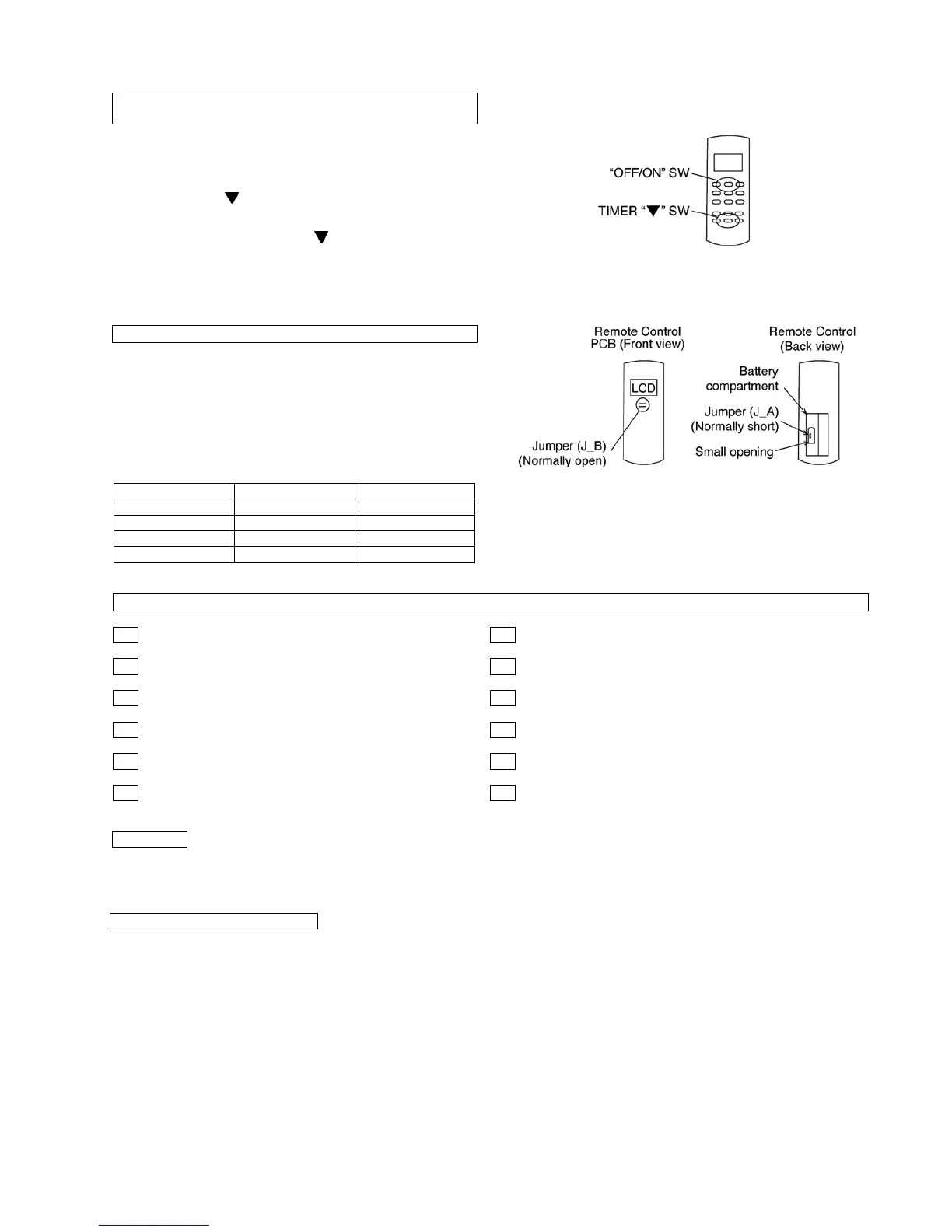
Con TIMER “ ” SW continuously for 5 seconds. Reset
code will be transmitted. After the reset code is
transmitted, release TIMER “ ” SW.
3. Press Remo-Con “OFF/ON” button. The new Remo-Con
No. will be accepted and memorized, after which the new
Remo-Con No. can be used.
1. Remove the batteries from the battery compartment of
the Remote Control.
2. On the left side of the battery compartment, there is a
small opening in the centre in which Jumper (J_A) can be
seen. In the accepted Remo-Con PCB shown beside,
Jumper (J_B) can be seen.
• Teach the customer the operation and maintenance procedures, using the operation manual (air filter cleaning, temperature
control, etc.)
• With regards to installation of the parts sold separately, follow the installation manual which is provided with the parts sold
separately.
CHANGING THE REMOTE CONTROL TRANSMISSION
CODE
REMO-CON NO. CHANGE IN REMOTE CONTROL
J_A J_B Remo-Con No.
Short Open A (Default)
Open Open B
Short Short C
Open Short D
CHECK ITEMS
Is there any gas leakage at flare nut connections? Is the cooling/heating operation normal?
Has the heat insulation been carried out at flare nut connections? Is the indoor unit properly secured to the installation plate?
Is the connecting cable being fixed to the terminal board firmly? Is the power supply voltage complied with rated value?
Is the connecting cable being clamped firmly? Is there any abnormal sound?
Is the drainage OK? Is the thermostat operation normal?
Is the Earth wire connection properly done? Is the remote control’s LCD operation normal?
HAND OVER
As to parts to be sold separately