59
16 Disassembly and Assembly Instructions
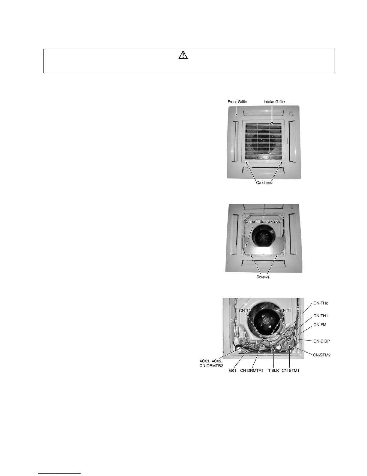
16.1. Disassembly of Parts
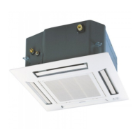
1. Open the Intake Grille from the Front Grille by moving the
catchers to center (Fig.1).
2. Remove the Control Board Cover by removing the screws
(Fig. 2).
3. Release the (Fig. 3):
• CN-STM1 (WHT) connector.
• CN-STM2 (YLW) connector.
• CN-DISP (WHT) connector.
• CN-FM (WHT) connector.
• CN-TH1 (WHT) connector.
• CN-TH2 (BLU) connector.
• CN-DRMTR1 (BLU) connector.
• AC01 (BLK), AC02 (WHT) and CN-DRMTR2 (RED) from
Terminal Board.
• G01 (GRN) screw.
• Two T-BLK connectors.
• CN-T1 (WHT).
• CN-T2 (YLW).
Fig. 1
Fig. 2
Fig. 3
WARNING
High Voltage are generated in the electrical parts area by the capacitor. Ensure that the capacitor has discharged sufficiently before proceeding
with repair work. Failure to heed tis caution may result in electric shocks.