63
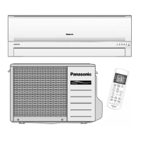
Fig. 5
Fig. 6
Fig. 7
Fig. 8
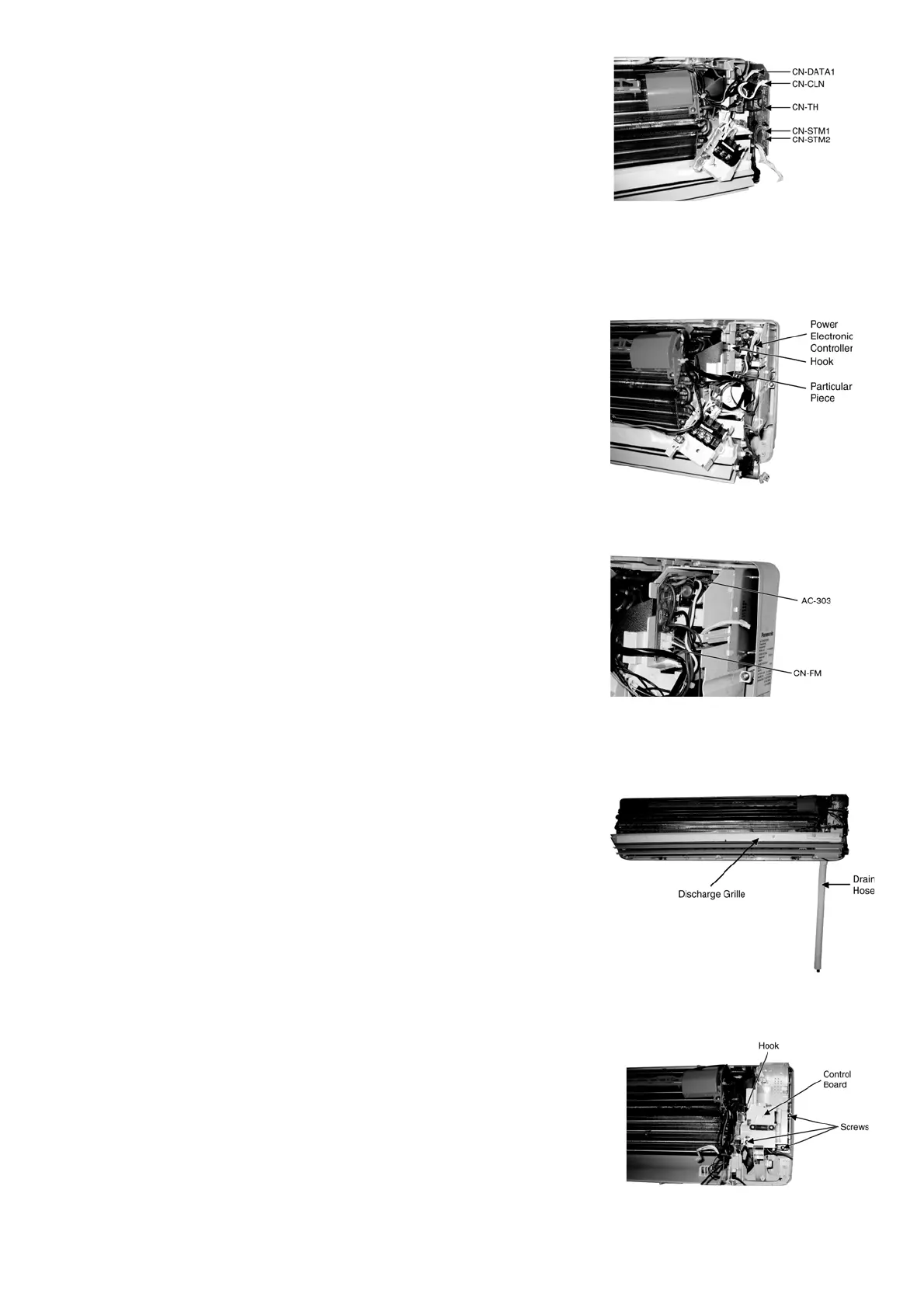
Fig. 9
• Release the CN-DATA1 connector (Fig. 5)
• Release the CN-TH connector (Fig. 5)
• Release the CN-CLN connector (Fig. 5)
• Release the CN-STM1 connector (Fig. 5)
• Release the CN-STM2 connector (Fig. 5)
16.2.3 To Remove the Power Electronic Controller
• Release the hook that hold the Particular Piece and pull out the Power
Electronic Controller. (Fig. 6)
• Release the AC-303 connector. (Fig. 7)
• Release the CN-FM connector. (Fig. 7)
16.2.4 To Remove the Discharge Grille
• Pull out the Drain Hose (behind the Discharge Grille) from outlet to
remove the Discharge Grille. (Fig. 8)
16.2.5 To Remove the Control Board
• Release the 3 screws (Fig. 9)
• By pressing down the hook at the left hand side, you will be able to
remove the Control Board. (Fig. 9)