181
19.5 Outdoor Electronic Controller Removal Procedure
19.5.1 CU-TZ20ZKE CU-TZ25ZKE CU-TZ35ZKE CU-TZ42ZKE CU-RZ25ZKE
CU-RZ35ZKE
Caution! When handling electronic controller, be careful of electrostatic discharge.
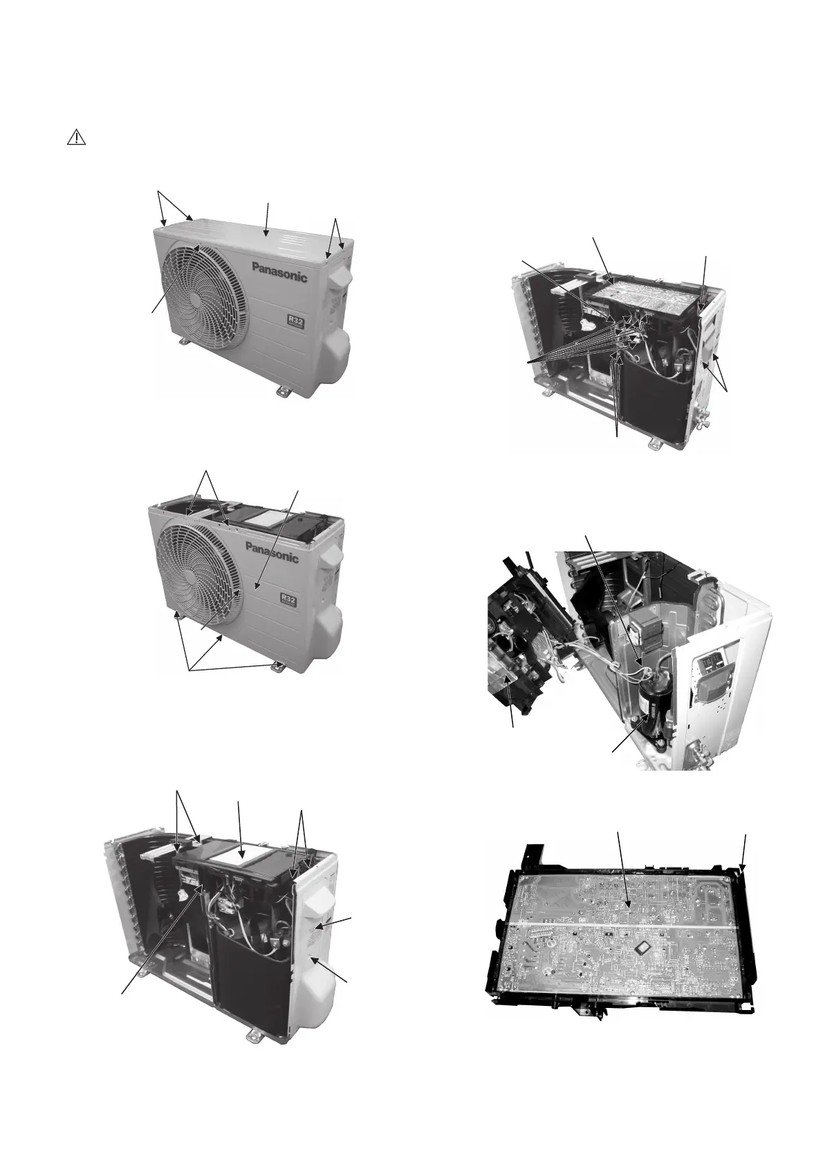
1 Remove the 5 screws of the Top Panel.
Fig. 1
2 Remove the 6 screws of the Front Panel.
Fig. 2
3 Remove the screw of the Terminal Board
Cover.
4 Remove the Top Cover of the Control Board
by 4 hooks.
Fig. 3
5 Remove the Control Board as follows:
Fig. 4
Fig. 5
Fig. 6
Top Panel
Screws
Screw
Screws
Screws
Screws
Screw
Front Panel
Hooks
Top Cover
Hooks
Terminal
Board
Cover
Screw
Control Board
Control Board
Release 3 Terminal
Connectors, L, N
and Earth Wire Screw.
Then Remove 4 Terminal
Connectors of DRM.
Remove 2
Screws of
Plate Terminal
Board
Remove of Screw
Control Board
Release 2 Earth
Wire Screws
Release 7
Connectors
e
ve t
e
e
i
lC
ve
and 3 Terminal Compressor
Control Board
Compressor
l
ct
o
ic
o
t
oll
Control Board
 Loading...