38
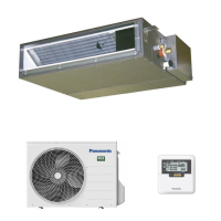
12. Installation Instruction
■ Required Materials
Read the catalog and other technical materials
and prepare the required materials.
Applicable piping kit
Applicable piping kit
Piping size
Gas Liquid
CZ-3F5, 7BP 9.52 mm (3/8") 6.35 mm (1/4")
CZ-4F5, 7, 10BP 12.7 mm (1/2") 6.35 mm (1/4")
CZ-52F5, 7, 10BP 15.88 mm (5/8") 6.35 mm (1/4")
Pipe Size Reducer (CZ-MA1P) and Expander
(CZ-MA2P) for Outdoor Multi Connection
CS-Z50******, CS-Z60******.
Please refer to “Connect the piping”.
■ Other Items to be Prepared (Locally Purchased)
Product name Remarks
Rigid PVC pipe VP20 (outer diameter ø26); also
sockets, elbows and other parts as
necessary
Adhesive
PVC adhesive
Insulation For refrigerant piping insulation :
foamed polyethylene with a thickness of
8 mm or more.
For drain piping insulation : foamed
polyethylene with a thickness of 10 mm
or more.
Indoor/outdoor
connecting cable
4 x 1.5 mm
flexible cord, designation
type 60245 IEC 57 (H05RN-F)
Hanging bolt related
parts
Hanging bolts (M10) (4) and nuts (12),
(when hanging the indoor unit)
Table A
Model Capacity
Indoor A
min
(m
2
)
2.2m for ducted 2.5m for ducted
Z25****** 1.0HP 0.64 0.50
Z35****** 1.5HP 0.71 0.55
Z50****** 2.0HP 1.37 1.06
Z60****** 2.25HP 1.37 1.06
* Table “A” only applicable for single split connection.
* In case of connection to outdoor multi inverter, refer
to installation manual at outdoor unit.
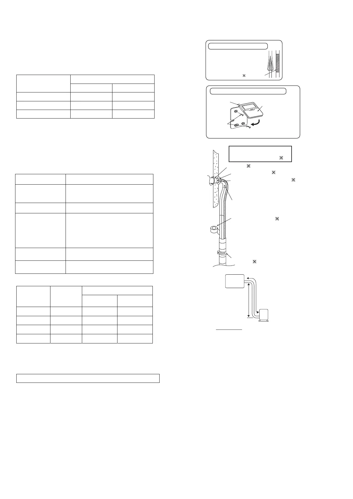
Attaching the remote controller to the wall
Screws 3
or
screws 4
Remote controller
cable 2
Remote controller 1
Details refer to
3. INSTALLING
THE INDOOR
UNIT (Remote
Control
Installation)
Insulation of piping connections
• Carry out insulation after
checking for gas leaks and
secure with vinyl tape.
Vinyl tape
Sleeve ( )
Bushing-Sleeve (
)
Putty (Gum Type Sealer) (
)
Bend the pipe as closely on
the wall as possible, but be
careful that it doesn’t break.
Vinyl tape (Wide) (
)
• Apply after carrying out
a drainage test.
• To carry out the drainage
test, remove the air
fi lters and pour water
into the heat exchanger.
Saddle (
)
Installation parts you
should purchase (
)
A
Indoor
unit
B
Outdoor
unit
IMPORTANT
Begin the installation job from
the “Indoor Unit” installation.
•
This illustration is for
explanation purposes only.
The indoor unit will actually
face a different way.
A
min
= (M / (2.5 × (LFL)
(5/4)
× h
0
))
2
A
min
= Required minimum room area, in m
2
M
= Refrigerant charge amount in appliance, in kg
LFL
= Lower flammable limit (0.306 kg/m
3
)
h
0
= Installation height of the appliance: (2.2m for ducted is standard reference installed height)
(2.5m for ducted is minimum installed height given by manufacturer)
 Loading...