
W
weaverannAug 5, 2025
What to do if the Panasonic CS-Z25UB4EAW condenser is dusty?
- RRaymond GarciaAug 5, 2025
If your Panasonic Air Conditioner's condenser is dusty and preventing heat radiation, you should clean the condenser.
What to do if the Panasonic CS-Z25UB4EAW condenser is dusty?
If your Panasonic Air Conditioner's condenser is dusty and preventing heat radiation, you should clean the condenser.
What to do if my Panasonic Air Conditioner has insufficient refrigerant?
If your Panasonic Air Conditioner has insufficient refrigerant, check for leaks or refill refrigerant.
What to do if my Panasonic CS-Z25UB4EAW has too much refrigerant?
If your Panasonic Air Conditioner has an excessive amount of refrigerant, you should adjust the refrigerant amount.
How to fix a clogged strainer or capillary tube in my Panasonic CS-Z25UB4EAW Air Conditioner?
If your Panasonic Air Conditioner's strainer or capillary tube is clogged, clear the blockage.
What to do if my Panasonic CS-Z25UB4EAW Air Conditioner compressor is inefficient?
If your Panasonic Air Conditioner compressor is inefficient, consider replacing or repairing the compressor.
Qualifications and supervision requirements for handling refrigerants.
Safety checks and procedures for working with flammable refrigerants.
Procedures for checking for flammable atmospheres and leak detection.
Requirement for having fire extinguishing equipment available.
Avoiding ignition sources near refrigerant systems.
Ensuring adequate ventilation during work on refrigerant systems.
Checks for electrical components and equipment specifications.
Initial safety checks for electrical components and wiring.
Procedures for repairing sealed components, including electrical safety.
Guidelines for repairing intrinsically safe components while live.
Checking cabling for wear, corrosion, or other environmental effects.
Methods for detecting flammable refrigerants and avoiding ignition sources.
Using electronic leak detectors and safety precautions.
Procedures for removing and evacuating refrigerant circuits.
Procedures for charging refrigerant systems, including safety.
Procedures for safely decommissioning refrigeration equipment.
Requirements for labelling de-commissioned equipment.
Procedures for recovering refrigerant safely and correctly.
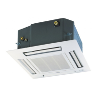
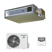
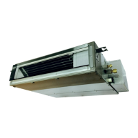
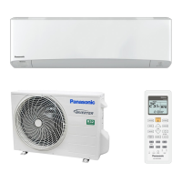
Identifies controls and components on the indoor unit.
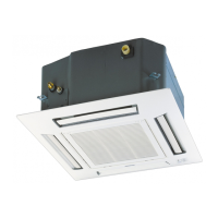
Identifies controls and components on the outdoor unit.
Explains the functions of buttons and display on the remote control.
Provides detailed dimensions and mounting information for the indoor unit.
Provides detailed dimensions and installation space for outdoor units.
Illustrates the refrigeration cycle for specific indoor/outdoor unit combinations.
Illustrates the refrigeration cycle for other indoor/outdoor unit combinations.
Shows the block diagram for specific indoor/outdoor unit combinations.
Shows the block diagram for other indoor/outdoor unit combinations.
Details the wiring connections for the indoor unit.
Details wiring connections for outdoor units.
Presents the electronic circuit diagram for the indoor unit.
Presents the electronic circuit diagram for outdoor units.
Shows the layout of the main and display printed circuit boards for the indoor unit.
Shows the main printed circuit board layout for outdoor units.
Instructions for installing the indoor unit, including required materials.
Guidelines for selecting the optimal location for indoor unit installation.
Details ceiling opening dimensions and refrigerant piping installation.
Steps and precautions for brazing and connecting refrigerant piping.
Instructions for connecting and testing the indoor unit's drain piping.
Guidance on performing heat insulation for drain, liquid, and gas piping.
Instructions for connecting the power supply and communication cables.
Steps for fitting the decorative panel onto the indoor unit.
Procedures for connecting refrigerant piping to indoor and outdoor units.
Connecting piping for multi-split outdoor unit combinations.
Instructions for installing the outdoor unit, including location selection.
Guidelines for selecting the optimal location for the outdoor unit.
Steps for physically mounting and securing the outdoor unit.
Procedures for connecting refrigerant piping to the outdoor unit.
Procedure for evacuating air from the system using a vacuum pump.
Instructions for connecting power supply and inter-unit cables.
Guidance on insulating piping to prevent water condensation.
Instructions for cutting and flaring copper pipes for refrigerant lines.
Recommendations for disposing of drain water and using drain elbows.
Information on R32 refrigerant and its environmental impact.
Chemical characteristics and properties of R32 refrigerant compared to others.
Lists required tools and procedures for refrigerant piping.
Lists common tools required for R32 refrigerant piping installation and services.
Details specific tools like flare gauges and flare tools for R32/R410A.
A summary of tools used for refrigerant piping installations and services.
Covers new installation, relocation, and repair of refrigerant cycle systems.
Details on R32 pipe materials, flaring, processing, and connection.
Details on pipe materials, thickness regulations, and flaring procedures.
Steps and precautions for processing and connecting refrigerant pipes.
Procedures for installing, relocating, and servicing air conditioners.
Procedure for air purging and gas leak testing during new installation.
Step-by-step process for recovering refrigerant using a recovery device.
Steps for removing and reinstalling the air conditioning unit during relocation.
Techniques and considerations for brazing refrigerant cycles.
Requirements and procedures for preparing for refrigerant cycle brazing.
Adjusting vacuum pump pressure settings for proper operation.
Steps to check gas provision for torches before brazing.
Adjusting the flame type and mixture for brazing work.
Description of different flame types (Neutral, Carbide, Oxidizing).
Procedures for safely closing the torch flame.
Table and guidance on selecting appropriate brazing materials.
Importance and function of flux in brazing.
Importance of nitrogen gas flow during brazing to prevent oxidation.
Criteria for checking brazing points for quality and gap space.
Methods for heating and applying brazing material correctly.
Definitions of terms related to brazing processes and defects.
Method for diagnosing issues without error codes.
Steps to prepare for diagnosing operational issues without error codes.
Explains the refrigerant cycle and how to verify its operation.
Table guiding diagnosis based on pressure, current, and temperature readings.
Explains basic inverter control and microcomputer functions.
Describes how internal setting temperature is determined and updated.
Details thermostat control for cooling operation.
Details thermostat control for soft dry operation.
Details thermostat control for heating operation.
Explains automatic operation mode decision logic.
Details fan motor operation and control.
Specifies manual and auto fan speeds in RPM for different modes.
Details outdoor fan motor operation logic.
Controls airflow direction.
Details automatic and manual vertical airflow direction settings.
Provides quiet operation modes for cooling.
Provides quiet operation mode for heating.
Enables powerful mode for quick temperature adjustment.
Manages ON and OFF timer settings.
Details how to set and use the ON timer function.
Details how to set and use the OFF timer function.
Automatic restart function after power interruption.
Explains the unit's indicator lights and panel.
Details the operation of the built-in drain pump.
Describes the HA terminal for digital connection to external devices.
Details thermostat control for cooling in multi-split setups.
Details thermostat control for soft dry in multi-split setups.
Details thermostat control for heating in multi-split setups.
Explains temperature sampling control for multi-split units.
Covers restart control and total running current protection.
Protection controls specific to cooling and soft dry modes.
Regulation of compressor frequency based on outdoor air temperature.
Detects outdoor pipe temperature to limit compressor operation frequency.
Compressor stop condition if indoor heat exchanger temperature is too low.
Conditions and actions for freeze prevention control.
Control to prevent dew formation at the indoor unit discharge area.
Control to reduce odor released from the unit.
Protection controls specific to heating operations.
Compressor frequency regulation based on intake air temperature.
Regulation of max current value based on outdoor air temperature.
Compressor frequency regulation based on indoor heat exchanger temperature.
Regulation of compressor frequency during low outdoor temperatures in heating.
Cold draught operation initiated by low indoor pipe temperature.
Deice operation starts when outdoor temperatures are low.
Protection control for low pressure conditions during heating.
How to use the Auto OFF/ON button for operations and settings.
Control of heating-only operation mode.
Steps to activate and deactivate the "Heat Only" operation mode.
Details functions of remote control buttons.
Using the SET button for transmission codes and temperature limit settings.
Restores remote control and unit settings to factory default.
Adjusts indicator LED intensity and display units.
Instructions for entering and using special setting modes.
Diagnosing malfunctions in the refrigeration cycle.
Functions for self-diagnosis of unit abnormalities.
Using alphanumeric codes for self-diagnosis of abnormalities.
Steps to initiate and perform a diagnosis using the remote control.
How to view stored error codes and protective operation history.
Procedure to clear memorized error codes after completing repairs.
Temporary operation of the unit during breakdown conditions.
Reference table of error codes and their causes.
Detailed troubleshooting steps for specific error codes.
Troubleshooting steps for H11 error (communication failure).
Troubleshooting steps for H12 error (capacity rank mismatch).
Troubleshooting steps for H14 error (indoor intake air sensor abnormality).
Troubleshooting steps for H15 error (compressor temperature sensor abnormality).
Troubleshooting steps for H16 error (outdoor current transformer issue).
Troubleshooting steps for H19 error (indoor fan motor locked).
Troubleshooting steps for H23 error (indoor pipe temperature sensor abnormality).
Troubleshooting steps for H24 error (indoor pipe temperature sensor 2 abnormality).
Troubleshooting steps for H27 error (outdoor air temperature sensor abnormality).
Troubleshooting steps for H28 error (outdoor pipe temperature sensor abnormality).
Troubleshooting steps for H30 error (compressor discharge temperature sensor abnormality).
Troubleshooting steps for H32 error (outdoor heat exchanger sensor 2 abnormality).
Troubleshooting steps for H33 error (unspecified voltage between units).
Troubleshooting steps for H36 error (outdoor gas pipe sensor abnormality).
Troubleshooting steps for H37 error (outdoor liquid pipe temperature sensor abnormality).
Troubleshooting steps for H97 error (outdoor fan motor locked).
Troubleshooting steps for H98 error (indoor high pressure/temp issue).
Troubleshooting steps for H99 error (indoor freeze prevention).
Troubleshooting steps for F11 error (4-way valve switching failure).
Troubleshooting steps for F17 error (indoor standby unit freezing).
Troubleshooting steps for F90 error (PFC protection).
Troubleshooting steps for F91 error (refrigeration cycle abnormality).
Troubleshooting steps for F93 error (compressor rotation failure).
Troubleshooting steps for F95 error (outdoor high pressure protection).
Troubleshooting steps for F96 error (IPM overheating).
Troubleshooting steps for F97 error (compressor overheating).
Troubleshooting steps for F98 error (input over current detection).
Troubleshooting steps for F99 error (DC peak detection).
Step-by-step guide for disassembling the indoor unit parts.
Performance data for the cooling mode under various conditions.
Performance data for the heating mode under various conditions.
Characteristic curves for cooling mode based on outdoor air temperature.
Characteristic curves for heating mode based on outdoor air temperature.
Correction factors for cooling and heating capacity based on piping length.
Exploded view and parts list for the indoor unit.
Exploded view and parts list for the CZ-BT20EW front grille.
Exploded view and parts list for outdoor units.
| Brand | Panasonic |
|---|---|
| Model | CS-Z25UB4EAW |
| Category | Air Conditioner |
| Language | English |