38
12. Installation Instruction
12.1 Indoor Unit
Required Materials
Read the catalog and other technical materials
and prepare the required materials.
Applicable piping kit
Applicable piping kit
Piping size
Gas Liquid
CZ-3F5, 7BP 9.52 mm (3/8") 6.35 mm (1/4")
CZ-4F5, 7, 10BP 12.7 mm (1/2") 6.35 mm (1/4")
CZ-52F5, 7, 10BP 15.88 mm (5/8") 6.35 mm (1/4")
o Pipe Size Reducer (CZ-MA1P) and Expander
(CZ-MA2P) for Outdoor Multi Connection
CS-Z50******, CS-Z60******.
o Please refer to “Connect the piping”.
Table A
Model Capacity
Indoor A
min
(m
2
)
2.2m for mini
cassette
2.5m for mini
cassette
Z25****** 1.0HP 0.64 0.50
Z35****** 1.5HP 0.71 0.55
Z50****** 2.0HP 1.37 1.06
Z60****** 2.25HP 1.37 1.06
* Table “A” only applicable for single split connection.
* In case of connection to outdoor multi inverter, refer
to installation manual at outdoor unit.
A
min
= (M / (2.5 x (LFL)
(5/4)
x h
0
))
2
A
min
= Required minimum room area, in m
2
M = Refrigerant charge amount in appliance, in kg
LFL = Lower flammable limit (0.306 kg/m
3
)
h
0
= Installation height of the appliance :
(2.2m for mini cassette is standard reference
installed height)
(2.5m for mini cassette is minimum installed
height given by manufacturer)
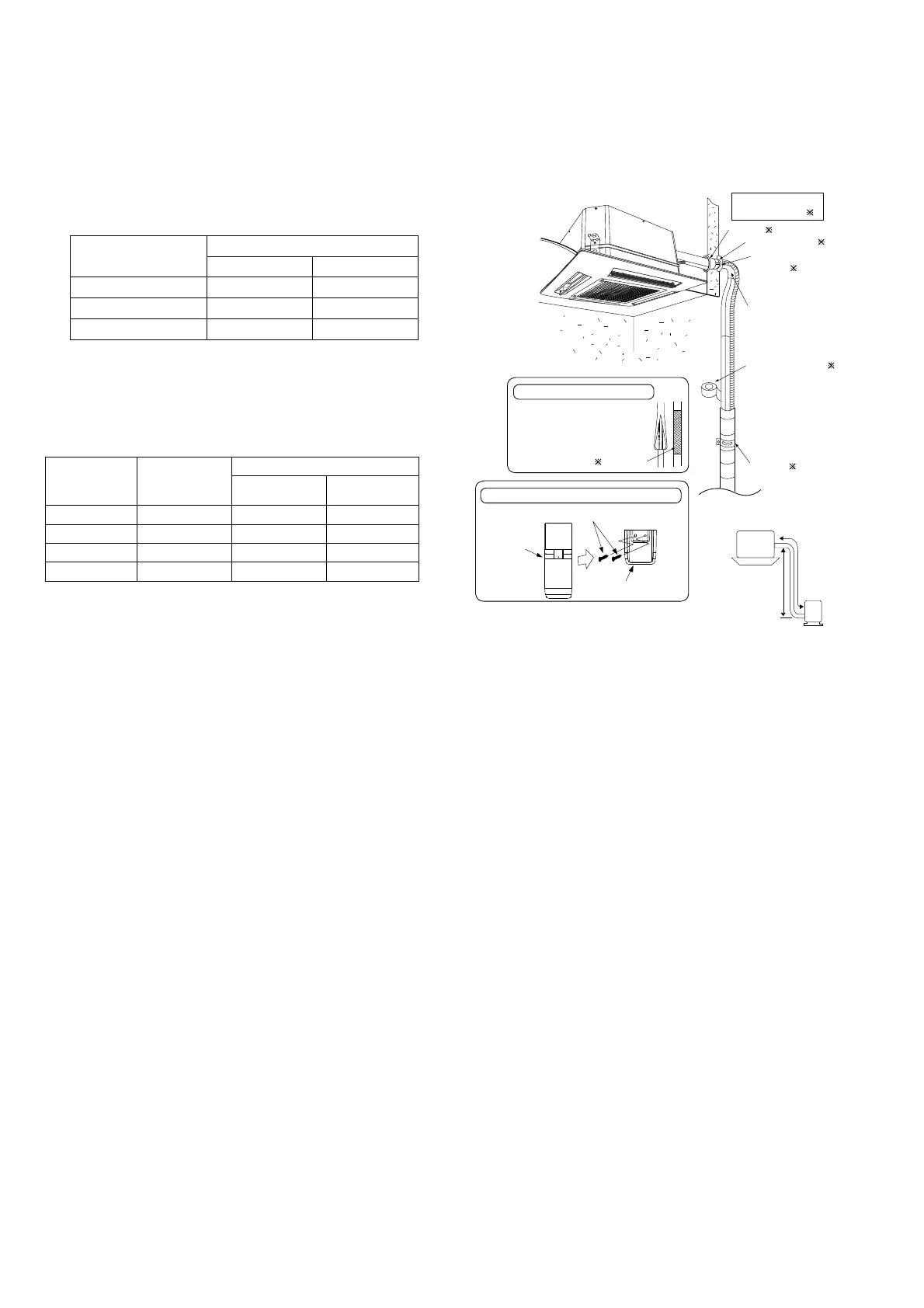
12.1.1 Indoor Installation Diagram
Installation parts you
should purchase (
)
Sleeve ( )
Bend the pipe as
closely on the wall as
possible, but be careful
that it doesn’t break.
Putty (Gum Type
Sealer) (
)
Bushing-Sleeve (
)
Vinyl tape (Wide) (
)
• Apply after carrying
out a drainage test.
Saddle (
)
a
Indoor unit
b
Outdoor
unit
Insulation of piping connections
• Carry out insulation after
checking for gas leaks and
secure with vinyl tape.
Vinyl tape
•
This illustration is for explanation purposes only.
The indoor unit will actually face a different way.
Remote control holder fixing screws
Remote control holder
Remote
control
Attaching the remote control holder to the wall
 Loading...