EasyManua.ls Logo

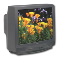
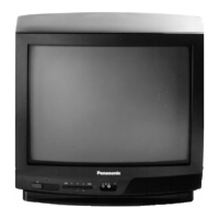
Panasonic CT-2511HDB

Panasonic CT-2511HDB
53 pages
To Next Page IconTo Next Page
Loading...
Panasonic
The service technician is required to read and follow the “Safety Precautions” and “Important Safety Notice” in this Manual.
Service Manual
Color Television
(NA6LM)
Simplified Manual
Copyright 2000 by Matsushita Electric Corporation of
America. All rights reserved. Unauthorized copying
and distribution is a violation of law.
WARNING! This Service Manual is designed for experienced repair technicians only and is not designed for use by the general public.
It does not contain warnings or cautions to advise non-technical individuals of potential dangers in attempting to service a product.
Products powered by electricity should be serviced or repaired only by experienced professional technicians. Any attempt to
service or repair the product or products dealt with in this Service Manual by anyone else could result in serious injury or death.”
Chassis
CT-2511HDB AP335
CT-2521HDB BP355
CT-2721HDB BP307
CT-3221HDB AP357
Models
ORDER NO. MTNC000929A1
B5
®
This Simplified Service manual is issued as a service guide for the models of the NA6LM family listed above. Included
in this manual are a set of schematic, functional descriptions, alignment procedures, disassembly procedures, and a
complete parts list. For Block Diagrams Refer to Main Manual MTC9905021C1 (CT-2720HA).
S
i
m
p
l
i
f
i
e
d
Appearance and inputs my vary depending on model
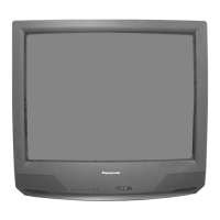
Table of Contents

Other manuals for Panasonic CT-2511HDB

Questions and Answers:

Panasonic CT-2511HDB Specifications

General IconGeneral
BrandPanasonic
ModelCT-2511HDB
CategoryCRT TV
LanguageEnglish

Summary

Safety Notices and Precautions

Important Safety Notice

Critical safety information for technicians regarding component replacement and hazards.

General Guidelines and Precautions

Essential safety guidelines and general advice for servicing electrical equipment.

Leakage Current Checks

Procedures for identifying electrical leakage hazards through cold and hot checks.

X-ray Radiation Hazards

Information on X-ray radiation hazards and precautions during servicing.

Horizontal Oscillator Disable Circuit

Overview of a protective circuit designed to prevent excessive high voltage.

Service Notes

Chip Component Handling

Guidelines for replacing surface-mount components due to critical foil track spacing.

Component Removal and Installation

Procedures for removing and installing chip components and leadless components.

Flat-IC Replacement Procedure

Step-by-step guide for replacing flat integrated circuits using specialized tools.

Horizontal Oscillator Disable Circuit Procedure

Detailed steps for checking the horizontal oscillator disable circuit's functionality.

Receiver Controls and Operation

Location of Controls

Identifies the physical controls and input jacks on the receiver's front panel.

Quick Reference Control Operation

Basic operation guide for power, volume, channel, action, and TV/video selection.

Disassembly and Component Identification

Disassembly for Service

General steps for disassembling the TV, including back cover and chassis removal.

Disassembly for CRT Replacement

Specific steps for disassembling the TV to replace the CRT.

CRT Component Replacement

Procedures for replacing the picture tube, including degaussing coil and ground braid.

Identification of Components

Locating key components such as boards, tuner, flyback, and yokes in the rear view.

Chassis Service Adjustments

Voltage Confirmation and Source Voltages

Checking critical voltage levels like 131.0V B+ and other source voltages.

Source Voltage Chart

Table of expected voltage readings at various test points under normal conditions.

Other Source Voltages

Details on 5V, 9V, and 12V standby voltages and their associated components.

High Voltage Check

Procedure for measuring high voltage, ensuring it is within specified limits.

Location of Components

Identifying components on the C-Board, DI-Board, Z-Board, and A-Board.

Purity and Convergence Procedures

Initial Static Convergence

Steps for setting initial static convergence using a dot/crosshatch generator.

Purity Adjustment

Procedure for adjusting picture purity using the Serviceman Mode.

Final Convergence Procedure

Steps for final convergence adjustments, including magnets and wedges.

Permalloy Convergence Corrector Strip

Using special strips to match the yoke and CRT for optimum convergence.

Serviceman Mode Operations

Serviceman Mode Entry and Toggling

How to access Serviceman Mode and toggle between Aging and Serviceman modes.

Serviceman Mode Adjustments Overview

Lists available electronic adjustments categorized into Sub-Data, Cut-Off, and MTS.

Purity Check Procedure

Steps to check picture purity using specific color screen modes.

Entering Serviceman Mode (Back-Open Method)

Alternative method for entering Serviceman Mode without opening the cabinet.

Instructional Flow Charts

Flow Chart for Serviceman Mode

Visual guide illustrating the process for entering and navigating Serviceman Mode.

Flow Chart for Serviceman Mode - Continued

Continuation of the visual guide for Serviceman Mode adjustments and exit procedures.

Electronic Control Adjustments

Sub-Brightness and Video Adjustment Level

Adjusting brightness, picture controls, and video adjustment level.

Sub-Contrast and TintColor Adjustment

Adjusting sub-contrast, tint, and color settings using specific waveforms.

Color Temperature Adjustment

Adjusting grayscale and warm highlights for proper color temperature tracking.

Horizontal Centering and Audio Adjustment

Adjusting picture horizontal centering and audio levels for optimal performance.

Clock Adjustment and Vertical Size

Adjusting clock frequency and vertical picture size for display accuracy.

Mechanical Control Adjustments

VCO Field Alignment

Procedure for adjusting the VCO for proper field alignment using an antenna signal.

Focus Adjustment

Adjusting the picture focus control to obtain the sharpest and clearest dot pattern.

Hotel Mode Feature

Clone Box Usage

How to use a clone box to upload and download TV settings for hotel environments.

Setting the Master Television

Steps to prepare a master television for cloning its settings.

Uploading and Downloading Settings

Procedures for transferring TV settings using the clone box (LEARN and TEACH).

Volume Limit Settings

Adjusting maximum volume levels for individual televisions in hotel mode.

Switching Modes (HotelNormal)

Procedures for switching the TV between Commercial (Hotel) and Normal TV modes.

IC Pinouts and Functions

IC101 VCJ Pinout and Functions

Detailed pin description and functions for the IC101 VCJ integrated circuit.

IC001 MPU Pinout and Functions

Detailed pin description and functions for the IC001 MPU integrated circuit.

Schematics and Diagrams

C-Board Schematic and Voltages

Electrical diagram and voltage readings for the C-board.

A-Board Schematic (LeftRight)

Electrical diagram for the A-board, covering left and right portions.

A-Board Waveforms

Signal waveforms for troubleshooting and diagnostic purposes on the A-board.

A-Board Voltages

Voltage measurements for various components on the A-board.

Schematic Notes

General notes applicable to schematic diagrams, including component symbols.

Related product manuals