26
d
b
d
b
a
c
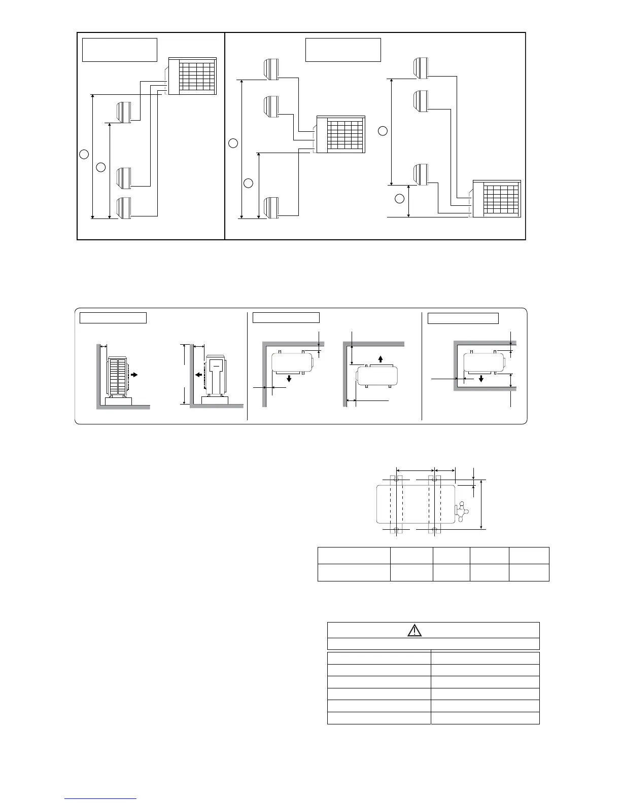
Outdoor unit
Outdoor unit
Outdoor unit
Indoor unittinuroodnI
Indoor unit
Outdoor unit located
on upper side
Outdoor unit located
otherwise
Outdoor Unit Installation Guidelines
Where a wall or other obstacle is in the path of outdoor unit’s intake or exhaust airflow, follow the installation
guidelines below.
For any of the below installation patterns, the wall height on the exhaust side should be 1200 mm or less.
More than 100
we
ivp
oTw
e
ived
i
S
1200
or
less
More than 1000
More than 100 More than 1000
More than 100
More than 300
More
than 100
More than 1000
More than 100
To p vi ew
it : mm
Wall facing one side
Wall facing two side
Wall facing three side
11.2 Install The Outdoor Unit
After selecting the best location, start installation
to Indoor/Outdoor Unit Installation Diagram.
1. Fix the unit on concrete or rigid frame firmly
and horizontally by bolt nut (ø10 mm).
2. When installing at roof, please consider strong
wind and earthquake.
Please fasten the installation stand firmly with
bolt or nails.
B
C
D
Model A B C D
CU-3TZ52*** 613 mm 131 mm 22 mm 360.5 mm
11.3 Connect The Piping
Remove the control board cover (resin) from the
unit by loosening three screws.
Connecting The Piping To Outdoor Unit
Decide piping length and then cut by using pipe
cutter. Remove burrs from cut edge. Make flare
after inserting the flare nut (locate at valve) onto
the copper pipe.
Align center of piping to valves and then tighten
with torque wrench to the specified torque as
stated in the table.
CAUTION
Do not over tighten, overtightening may cause gas leakage
Piping size Torque
1/4" (6.35 mm) [18 N•m (1.8 kgf•m)]
3/8" (9.52 mm) [42 N•m (4.3 kgf•m)]
1/2" (12.7 mm) [55 N•m (5.6 kgf•m)]
5/8" (15.88 mm) [65 N•m (6.6 kgf•m)]
3/4" (19.05 mm) [100 N•m (10.2 kgf•m)]