31
11.6 Heat Insulation
1. Please carry out insulation at pipe connection portion as mentioned in Indoor/Outdoor Unit Installation
Diagram. Please wrap the insulated piping end to prevent water from going inside the piping.
2. If drain hose or connecting piping is in the room (where dew may form), please increase the insulation by using
POLY-E FOAM with thickness 6 mm or above.
Refrigerant tubing shall be protected against mechanical damage.
CAUTION
Use a material with good heat-resistant properties as the heat insulation for the
pipes. Be sure to insulate both the gas-side and liquid-side pipes. If the pipes are
not adequately insulated, condensation or water leakages may occur.
Liquid-side pipes
Material shall
withstand
120°C or higher
Gas-side pipes
CUTTING AND FLARING THE PIPING
1. Please cut using pipe cutter and then remove the burrs.
2. Remove the burrs by using reamer. If burrs is not removed, gas leakage may be caused.
Turn the piping end down to avoid the metal powder entering the pipe.
3. Please make flare after inserting the flare nut onto the copper pipes.
■
Inclined Surface
damaged
Cracked Uneven
thickness
Bar
Red arrow mark
Handle
Core
Yo k e
Clamp
handle
Bar
0–0.5mm
Copper pipe
When properly flared, the internal surface
of the flare will evenly shine and be of
even thickness. Since the flare part come
into contact with the connections, carefully
check the flare finish.
Reamer
2. To remove burrs 3. To flare
Point down
Pipe
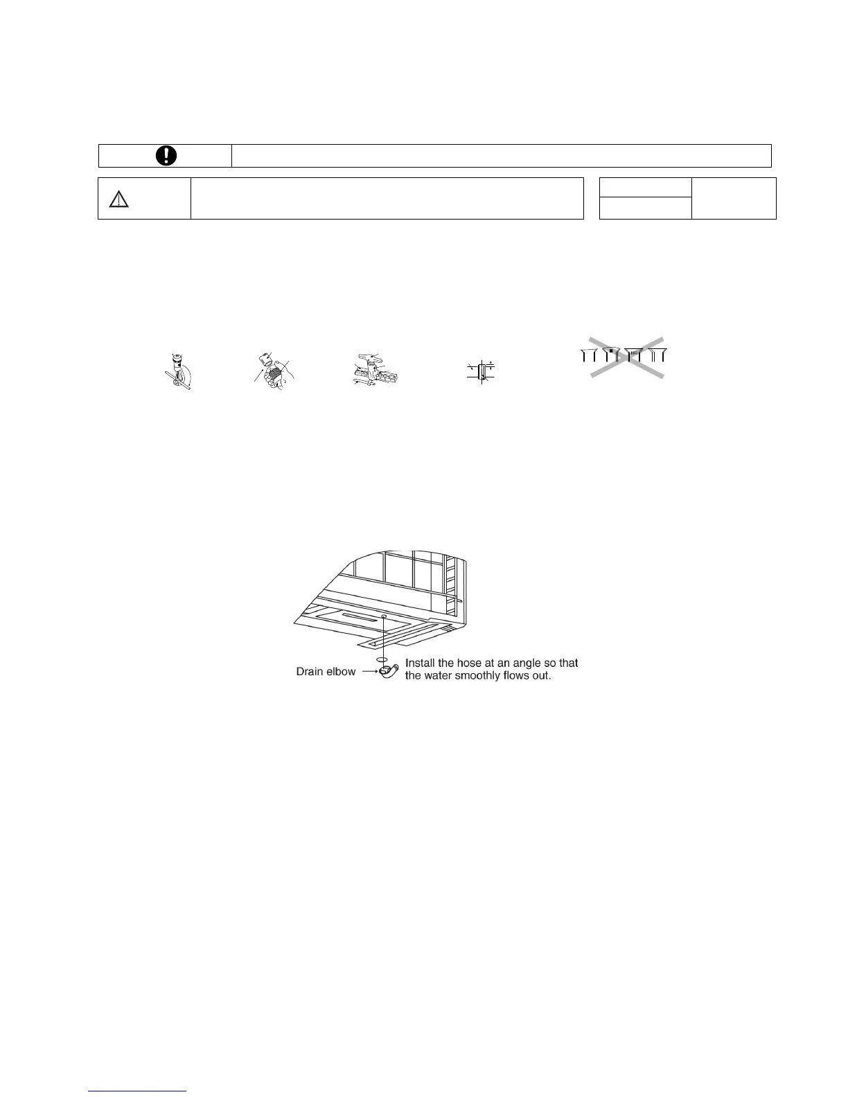
11.7 Disposal of Outdoor Unit Drain Water
If a drain elbow is used, the unit should be placed on a stand which is taller than 5 cm.
If the unit is used in an area where temperature falls below 0°C for 2 or 3 days in succession, it is recommended
not to use a drain elbow, for the drain water freezes and the fan will not rotate.