Do you have a question about the Panasonic CZ-CGLSC1 and is the answer not in the manual?
Instructions to read before installation for safety and correct operation.
Symbol refers to hazard/unsafe practice resulting in severe personal injury or death.
Symbol refers to hazard/unsafe practice resulting in personal injury or property damage.
Indicates actions or conditions that are forbidden during installation or operation.
Critical safety warnings for installation, including turning off power and professional installation.
Guidelines for repairs, specifying authorized parts and methods.
Prohibits use of torch detectors for refrigerant leak checks.
Emphasizes secure installation and proper electrical work by authorized personnel.
Instructions for handling abnormal conditions like burning smell.
Precautions when using flammable refrigerants in unventilated areas.
Avoid operating with wet hands or splashing water on the unit.
Lists locations that may cause severe decrease in functionality or damage.
Ground yourself to discharge static electricity before performing wiring.
Avoid direct sunlight, extreme temperatures, and specific atmospheric conditions.
Install the sensor unit horizontally.
Avoid exposure to silicone gases, organic solvents, and alkaline mist.
Do not block the gas detector; ensure proper ventilation during alarms.
Keep the air conditioner powered on for sensor operation.
Ventilate and evacuate immediately if a leak is suspected.
Remove all naked flames if a leak is suspected.
Details of the model number, physical dimensions, and weight.
Specifies the temperature and humidity range for operation.
Indicates the power supply requirements for the sensor unit.
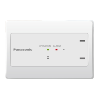
Identifies and describes the function of each part of the sensor unit.
Lists the sensor unit, installation instructions, operating instructions, and clampers.
Details regulations, spacing, height, and horizontal installation.
Specifies dimensions and placement relative to the floor.
Provides visual guidance on suitable and unsuitable installation spots.
Lists locations to avoid due to environmental factors or potential damage.
Shows basic wiring for external alarm output and remote controller.
Details wiring type, length, and connection limits for remote controllers.
Specifies wiring type and length for external output connections.
Illustrates incorrect wiring configurations that must be avoided.
Instructions for securely tightening screws without overtightening.
How to insert wiring into the terminal board using push buttons.
Procedure for detaching the top case using a flat-blade screwdriver.
Securing the bottom case to an embedded wall switch box.
Connecting the remote controller wiring to the RC terminal board.
Aligning and attaching the top case to the bottom case.
Procedure for connecting wiring to the Ext output terminal board.
Details sensor unit side terminals and external equipment connections.
Describes how LEDs, buzzer, and outputs behave based on sensor status.
Explains alarm conditions, buzzer stopping, and service life.
Warnings regarding gas alarms, abnormal behavior, and contact for service.
Details the meaning of LED lights for monitoring, leaking, and abnormal states.
Provides solutions for different status conditions like preparing or service life exceeded.
Procedure to confirm sensor unit operation after installation.
Guides through checks for power, communication, abnormalities, and leaks.
| Brand | Panasonic |
|---|---|
| Model | CZ-CGLSC1 |
| Category | Accessories |
| Language | English |