6-3
66
* It is not necessary to disconnect the communications line in the inter-unit control wiring if it has already been con-
nected at this time.
* Settingmodes1and2canbeusedevenwhentheoutdoorunitisindependent(when1maintenanceremotecon-
troller is connected to 1 outdoor unit and automatic address setting for the indoor units has not been completed).
* Displays the overall system status for that refrigerant system.
* “
” is displayed until auto address setting is completed.
6-3. Normal Display Operations and Functions
Normal display functions
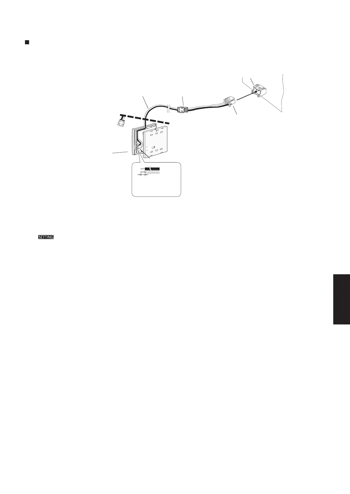
• ConnectthespecialservicecheckerwiringtotheoutdoorunitPCB.
The connection is shown in the figure below.
When connecting the special service
checker wiring to the remote controller
CZ-RTC4, cut out the wire as shown in the
figure below because the connector of the
remote controller cannot be used directly.
Special service
checker wiring
Top case
(Back side)
CZ-RTC4
(2P, WHT)
6 mm
Remove the coating.
Approx. 6 mm
Bottom case
(Back side)
CUT
Relay connector
(2P, WHT)
RC
(3P, BLU)
PCB connector
(3P, BLU)
Outdoor unit PCB
Terminal board
SM830276-00_欧州向け R32シングル TD&SM.indb 3 19/02/12 15:38:55
 Loading...