88
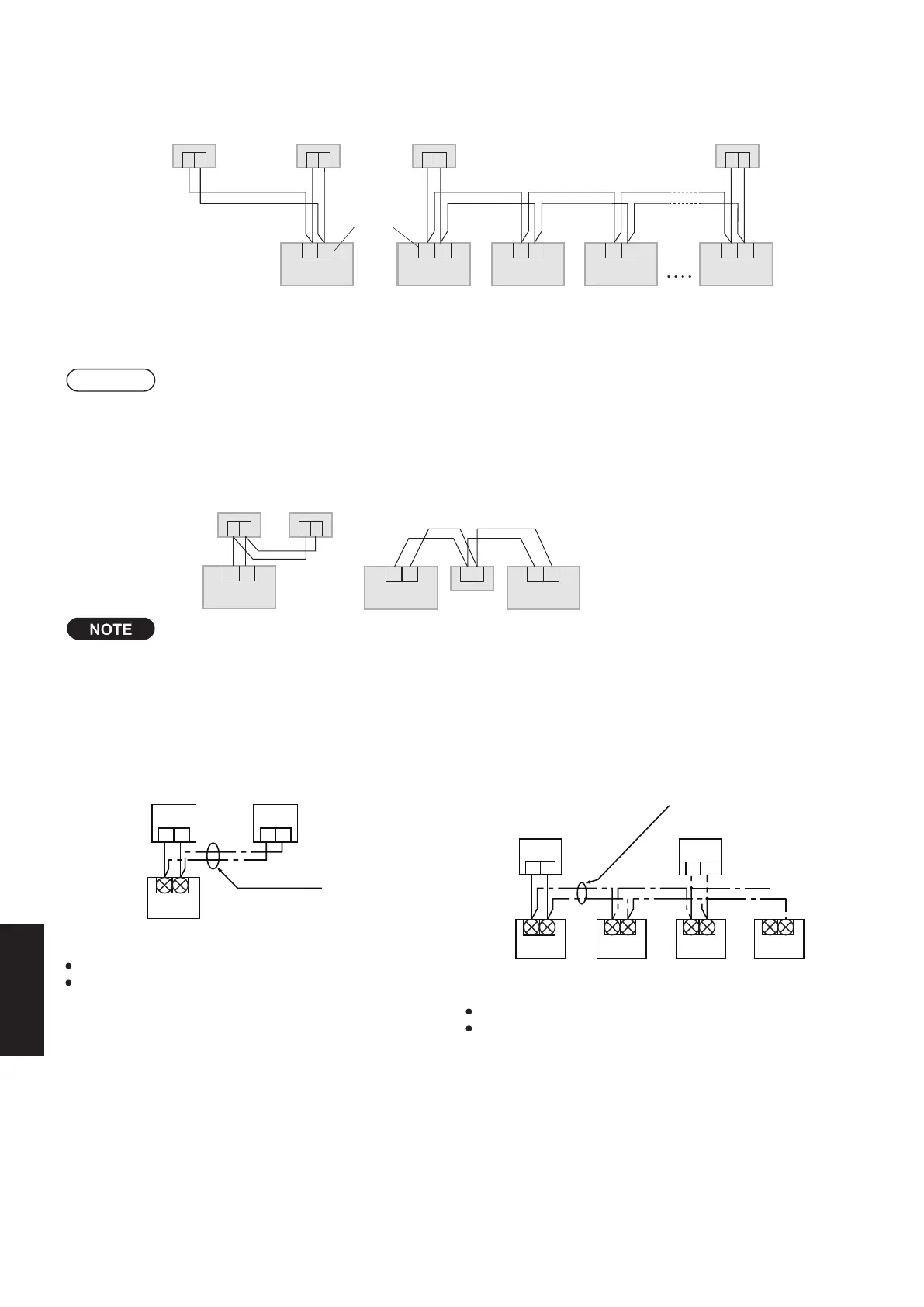
If a group of units are to be controlled by 2 remote controllers:
* Main/sub remote controllers will work regardless of which indoor
unit they are installed.
Use wiring of 0.5 mm
2
to 2 mm
2
for field supply.
Make the total wire length when cross-wiring a group no
more than 200 m.
When 1 indoor unit is operated by 2 remote controllers:
* Either of the remote controllers can be set to main/sub.
Use wiring of 0.5 mm
2
to 2 mm
2
for field supply.
Use a total wire length of no more than 400 m.
CN1
1 2 1 2
Wireless Remote Controller Kit
Wired Remote Controller
(Sold Separately)
Receiver
(Sold Separately)
Remote Controller Wiring
(Field Supply)
Indoor Unit
* (Main)
* (Sub)
Wireless Remote
Controller Kit
1st Indoor
Unit
2nd Indoor
Unit
3rd Indoor
Unit
4th Indoor
Unit
* (Main)
* (Sub)
Cross-wiring Remote controllers for Group
Control (Field Supply)
Wired
Remote Controller
CN1
1 2 1 2
Installation when setting Main/Sub for the remote controller and the receiver
1 2 1 2
R1 R2R1 R2R1 R2R1 R2
RC wiring ( field supply)
• No polarity
Indoor unit Indoor unit Indoor unit Indoor unit
1 21 2
R1 R2
Terminals for
RC wiring
)buS( revieceR)buS( revieceR
)niaM( CR deriW)niaM( CR deriW
Indoor unit
Using 1 indoor unit
Using more than 1 indoor unit
RC wiring
(field supply)
• No polarity
Installation
example
After installation, according to the “Settings” section, set one to [Main] and the other to [Sub].
Setting the wired remote controller to [Main] is recommended.
Attention
Multiple wireless/infrared remote controllers cannot be used simultaneously for a single indoor unit.
Be careful not to connect cables to other terminals of indoor units (e.g. power source wiring terminal). Malfunction may occur.
Do not bundle together with the power source wiring or store in the same metal tube. Operation error may occur.
If noise is induced to the unit power supply, attach a noise filter.
* Wiring shown below is prohibited.
R1 R2
R1 R2 R1 R2
1 2 1 2
1 2
Wired RC Receiver
Indoor unit Indoor unit Indoor unit
RC wiring
Receiver
The remote controller and the receiver can be connected to any indoor unit for operation.
2. Settings
SM830256-00_Single_欧州小筺体 TD&SM.indb 16 16/12/28 13:40:31
Setting for Receiver
ScrewPCB cover
Receiver PCB
Main/Sub selector
switch for remote
controllers (4)*
OFF: Main
ON: Sub
Set its address
(1) to (3)
All set at OFF
when shipped
from the factory.
ON
1 2 3 4
Check the settings of the [S003] DIP switch on the
receiver’s PCB.
* Remove the cover from the receiver when
* When using the infrared remote controller and
the wired remote controller in combination,
set the wired remote controller to [Main].
performing the PCB settings.
Setting Address Switches
When more than 1 receiver is installed in the same room, setting addresses prevents interference.
For how to change addresses of wireless remote controllers, see the operating instructions of wireless / infrared remote
controllers.
To change the receiver’s address, remove the cover from the receiver’s PCB and set No.1 to No.3 of the [003] DIP switch
on PCB.
Remote
Controller
Address
Display
Address Address Address Address Address Address Address
ON/OFF
States
ALL
Position of
the receiver’s
address
switch
Receipt is
possible at
all of the
address
positions
1234
1 2 3 4
1 2 3 4
1 2 3 4
1 234
1 2 3 4
OFF ON
1 2 3456
8-33. CZ-RWSU3, CZ-RWRU3
1. Accessories
Supplied accessories
Wireless Remote
Controller
(1)
(1)
(2)
(2)
(1)
(1)
(1)
Remote Control
Holder
LR03 Size
Battery
Operating
Instructions
Quick
Reference
Wood Screw
M4 × 16
Clamper
(1)
Installation
Instructions
CZ-RWRU3
CZ-RWSU3
8-28
SM830276-00_欧州向け R32シングル TD&SM.indb 28 19/02/18 11:16:09
 Loading...