EasyManua.ls Logo

Panasonic EU6441-U1 - User Manual

Panasonic EU6441-U1
19 pages
Print Icon
To Next Page IconTo Next Page
Loading...
1 DIAGRAM OF MAIN PCB 2
2 CHECKING
3
3 DISASSEMBLY
8
4 REPLACE THE DRIVING UNIT
12
5 HOW TO ALLIGN WIRES
13
© 2005 Matsushita Electric Works Ltd. All rights
reserved. Unauthorized copying and distribution is a
violation of law.
EU6441-U1
6 CHECK THE OPERATION 16
7 INSTALL THE SAFETY COVER AND MACHINE COVER
16
8 FINAL OPERATION CHECKING
16
9 EXPLODED VIEW
17
10 REPLACEMENT PARTS LIST
18
Core Trainer Exercise Equipment
CONTENTS
Page Page
ORDER NO. HPD0512U64C1
Question and Answer IconNeed help?

Do you have a question about the Panasonic EU6441-U1 and is the answer not in the manual?

Summary

Diagram of Main PCB

Checking

No Operation Troubleshooting

Diagnostic steps for when the unit is unresponsive.

LED and Motor Troubleshooting

Diagnosing issues with controller LEDs and motor function.

Seat Recline Troubleshooting

Diagnosing problems with the seat's reclining function.

Speed Adjustment Troubleshooting

Diagnosing why speed settings are not adjustable.

LED Illumination Troubleshooting

Diagnosing when unit LEDs fail to light up.

Seat Recline Failure Troubleshooting

Steps to diagnose why the seat does not recline.

Noise Troubleshooting

Identifying and rectifying sources of operational noise.

Disassembly

Safety Cover Removal

Step-by-step guide to removing the seat's safety cover.

Seat Cushion Removal

Procedure for detaching and removing the seat cushion.

Reins and Front Panel Removal

Steps for removing the reins and front panel components.

Controller Case Removal

Process for safely removing the controller housing.

Seat Removal

Instructions for detaching the main seat assembly.

Machine Cover Removal

Steps to remove the main external machine covers.

Main PCB Case Removal

Procedure for accessing and removing the main PCB enclosure.

Elevation Cover Removal

Instructions for removing the cover related to seat elevation.

Seat Lift Removal

Steps for detaching the seat lift mechanism.

Driving Unit Removal

Procedure for removing the main driving unit.

Replace the Driving Unit

Safety Cover Removal for Driving Unit Replacement

Removing the safety cover as a preliminary step.

Machine Cover Removal for Driving Unit Replacement

Detaching the machine cover to access internal components.

Seat Removal for Driving Unit Replacement

Removing the seat to facilitate driving unit access.

Main PCB Case Removal for Driving Unit Replacement

Accessing the main PCB case as part of the replacement process.

Seat Lift Removal for Driving Unit Replacement

Detaching the seat lift before replacing the driving unit.

Driving Unit Removal

Final steps to remove the driving unit.

How to Align Wires

Aligning Seat Lift Sensor and Power Source Wires

Bundling sensor and power source wires for proper routing.

Aligning Multiple Wires with Insulated Ties

Securing various wires using insulated ties and tape.

Aligning Wires via PCB Case Bottom Hole

Routing and securing wires through the PCB case.

Aligning Power Source and Motor Wires

Securing power source and motor wires with ties.

Check the Operation

Performing Operation Check

Steps to verify unit functionality after service.

Install the Safety Cover and Machine Cover

Installing Covers

Reattaching safety and machine covers.

Final Operation Checking

Verifying Final Operation and Settings

Checking all aspects of operation after installation.

Exploded View

Replacement Parts List

Overview

This document is a service manual for the Panasonic Core Trainer Exercise Equipment, model EU6441-U1. It provides detailed instructions and diagrams for checking, disassembling, replacing parts, aligning wires, and performing final operational checks of the device.

Function Description

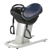
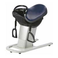
The Panasonic Core Trainer Exercise Equipment, EU6441-U1, is designed to provide core training exercises. While the manual does not explicitly detail the exercise functions, it implies a mechanism that involves a movable "Seat lift unit" and a "Driving unit" that facilitates changes in the seat's position and angle. The device is controlled via an "Operation PCB" and a "Controller" which allows users to select programmed courses or manual operations, and adjust speed. The "Seat lift unit" is responsible for reclining and relining the seat, indicating a dynamic movement feature essential for core training. The "Motor" is a key component in driving these movements, and various sensors (e.g., "Seat lift sensor") ensure proper and safe operation.

Important Technical Specifications

Based on the "10 REPLACEMENT PARTS LIST" and "2 CHECKING" sections, several technical specifications and components can be identified:

  • Motor Resistance Values: The motor coils have specific resistance values:
    • V-U (Red-Blue): 6.3 Ω
    • U-W (Blue-Yellow): 6.3 Ω
    • V-W (Red-Yellow): 6.3 Ω A deviation of more than ±10% from these values indicates a malfunction.
  • Power Source: The device uses a "Transformer" and a "Power source switch box" to manage its electrical supply. It also includes a "Power source wire" and "Connecting cord for Power source."
  • Control System: The core of the control system consists of a "Main PCB" and an "Operation PCB," along with a "Controller PCB." These PCBs are interconnected via various connectors (e.g., CN3, CN4, CN7, CN8, CN9, CN11, CN12, CN201, CN202).
  • Mechanical Components:
    • Seat Lift Unit: This unit is crucial for the seat's movement and includes a "Seat lift motor harness" and a "Seat lift sensor harness."
    • Driving Unit: This unit is responsible for the overall movement mechanism.
    • Fasteners: Various bolts and screws are used, with specific sizes mentioned for disassembly:
      • Grip fixing screws: 5mm (1/4") Hexagonal wrench.
      • Hexagonal bolts for seat removal: 13mm (1/2") socket wrench.
      • Upper Seat lift fixing bolts: 10mm (3/8") socket wrench.
      • Lower Seat lift fixing bolts: 13mm (1/2") socket wrench.
      • Supporting rod fixing bolt: 17mm (5/8") socket wrench.
      • Driving unit fixing bolts: 19mm (3/4") socket wrench.
  • Safety Features: The device incorporates a "Safety cover" and "Pushrivets" for secure installation and user protection.

Usage Features

The manual primarily focuses on service and maintenance, but some usage features can be inferred:

  • Programmed Courses: The "Controller" allows users to select "Programmed course" options, suggesting pre-set exercise routines.
  • Manual Course: A "Manual course" option is also available, indicating user-controlled operation.
  • Speed Adjustment: The "It operates but the speed cannot be adjusted" section implies that speed adjustment is a standard feature of the device.
  • LED Indicators: The "Controller" features "LEDs" and a "remaining time LED," which provide feedback to the user regarding operation status and exercise duration.
  • On/Off Switch: A main "On/off switch" is present for powering the device.
  • Seat Recline/Reline: The seat has the ability to recline and reline, which is a core function for the exercise variations. The manual notes that the "Seat angle becomes parallel right when the course is selected," indicating an automatic adjustment for starting positions.

Maintenance Features

The service manual is a comprehensive guide for maintaining the EU6441-U1, covering various aspects:

  • Troubleshooting (Checking): Detailed flowcharts are provided for diagnosing common issues such as "No operation," "All the LEDs on the Controller do not light and not work," "It operates but the speed cannot be adjusted," "It works properly, but LEDs do not light," "Seat does not recline even if the button is pushed," "Seat does not reline even if the button is pushed," and "Noises." These flowcharts guide technicians through systematic checks of components like the Main switch, Power cord, Connectors, Cord block, Controller block, Main PCB, Motor, Seat lift unit, and various harnesses.
  • Disassembly and Reassembly: Step-by-step instructions with accompanying diagrams are provided for disassembling and reassembling key parts, including the Safety cover, Seat cushion, Reins, Front panel, Controller case, Seat, Machine cover, Main PCB case, Elevation cover, Seat lift, and Driving unit. This ensures that components can be accessed for repair or replacement.
  • Part Replacement: The "4 REPLACE THE DRIVING UNIT" section specifically details the process of replacing the driving unit, which involves removing several other components first. The "10 REPLACEMENT PARTS LIST" provides a comprehensive list of all replaceable parts with their part numbers, descriptions, and quantities per unit.
  • Wire Alignment: The "5 HOW TO ALLIGN WIRES" section provides critical instructions and diagrams for correctly binding and aligning the Sensor wire, Power source wire, and Driving motor wire. Proper wire alignment is essential to prevent operational issues, short-circuits, and damage to components. This includes using insulated ties and black tape for securing wires.
  • Greasing: The "6 CHECK THE OPERATION" section includes a maintenance step for "Grease on the Screw of the Seat unit," specifying to apply grease from bottom to top and to avoid splashing it on other parts.
  • Final Operation Checking: After any service or repair, a "FINAL OPERATION CHECKING" procedure is outlined to ensure the machine functions correctly. This includes verifying the installation of all rivets, checking for irregular noises, and confirming that the seat angle automatically returns to parallel when the machine stops leaning.
  • Safety Precautions: The manual includes a prominent "WARNING" about the dangers of servicing electrical products without professional experience, emphasizing that only experienced technicians should perform repairs to prevent serious injury or death. It also includes cautions during operation, such as "Be careful not to hurt your fingers because the Seat angle becomes parallel right when the course is selected."

Panasonic EU6441-U1 Specifications

General IconGeneral
BrandPanasonic
ModelEU6441-U1
CategoryFitness Equipment
LanguageEnglish

Related product manuals