• The remote switching operation from the programming tool is operable.
• When performing remote switching from the programming tool, the setting of the mode switch and the
actual mode of operation may differ. Verify the mode with the status indicator LED.
• Restart FPΣ to operate in the mode set with the RUN/PROG. mode switch.
○
4
COM port baud rate switch
This switch is used to change the baud rate of the COM port between 115200 bps and 19200 bps.
Position of switch: On the left side; 115200 bps, On the right side; 19200 bps
○
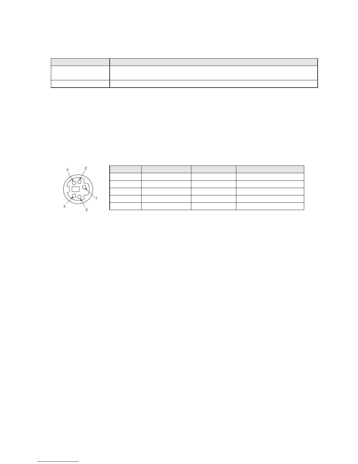
5 Tool port (RS232C)
This connector is used to connect a programming tool.
A commercial mini-DIN 5-pin connector is used for the tool port on the control unit.
- The followings are the default settings when the unit is shipped from the factory. The system register
should be used to change them.
Baud rate: 9600bps, Char. Bit: 8 bits, Parity check: Odd parity, Stop bit: bit
Note) The unit number of the tool port should be set by the system register.
○
6
Analog input connector (L40R, L40MR, L60R and L60MR types)
Connector for connecting an analog input cable.
○
7
COM port terminal (RS485: L40MR and L60MR types)
It is connected for using RS485 communication. Solderless terminals for M3 are used for connection. As
for the terminal unit, short-circuit the terminals of "E" and "-".
○
8
Service power supply for input (L30R, L40R, L40MR, L60R and L60MR types)
24 VDC power supply that can be used for the input circuit is output. Solderless terminals for M3 are
used for connection.
○
9
Output circuit terminal block
Terminals for output circuit. Solderless terminals for M3 are used for connection.
○
10
Expansion cover
It is removed/installed when installing the expansion cable and backup battery.
○
11
Input circuit terminal block
Terminals for input circuit. Solderless terminals for M3 are used for connection.
○
12
Power supply terminal block
Power supply terminals for driving the PLC internal circuit. A solderless terminal for M3 can be used.
○
13
DIN rail attachment lever
This lever enables the units to attach to a DIN rail at a touch.
○
14
Expansion connector (L40R, L40MR, L60R and L60MR types)
Connector for connecting the expansion I/O unit and expansion FP0 adapter.
○
15
Space and connector for installing battery (L40R, L40MR, L60R and L60MR types)
It is used for installing an optional backup battery.
 Loading...


