Table 2 Name and function of each switch on U-10MES2E8 outdoor unit control P.C.board
Function switch Remarks
RC plug (3P, BLU)
(CN73)
Connects to outdoor unit maintenance remote controller and content of alarm message will be
checked.
AP pin (2P, WHT)
(CN24)
Can be used when vacuuming the outdoor unit.
SNOW plug (3P, RED)
(CN34)
Can be used when installing a snowfall sensor device.
SILENT plug (2P, WHT)
(CN33)
Can be used when setting the outdoor unit fan in sound absorbing mode.
OC EMG terminal
(3P, BLK) (CN69)
If “TO INDOOR UNIT” accidently connected to high voltage, use the terminal base TM1.
Method: 1. Replace the pins 1 and 2 of CN69 with the pins 2 and 3.
2.. Disconnect J 1.
RC1 EMG terminal
(3P, BLK) (CN82)
If “TO OUTDOOR UNIT” accidently connected to high voltage, use the terminal base TM1.
Method: 1. Replace the pins 1 and 2 of CN82 with the pins 2 and 3.
. Disconnect JP12.
3..
Setting the Fuel Gas Type (If Band P (LPG) is Used)
* When using Band P (LPG) for fuel gas, the gas type has to be congured.
* The outdoor unit power breaker remains OFF.
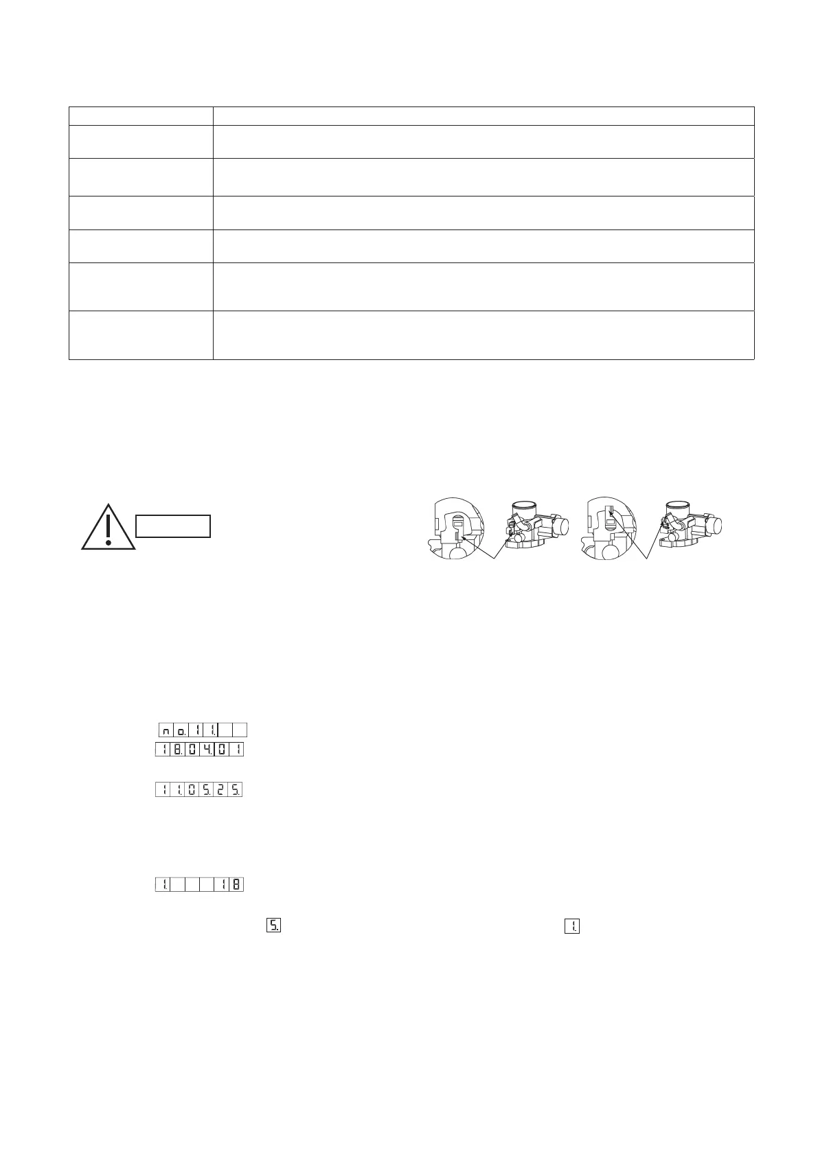
(1) Move the lever of the N/P switch that is attached to the mixer part of the engine to the position shown in the diagram.
Turn it 180 degrees in the anticlockwise direction (there is a stopper provided). Do not apply unnecessary force to turn it
any further.
After installing, be sure to
check that there is no gas
leakage. There is the danger
of fire if gas leaks
(2) Mount the attached short-circuit connector to the
N/P switch (Fig. 1) of the outdoor control board.
* Switch on the power breaker of the outdoor unit.
(3) Apply the < Gas type set and adjusted > label in the PL NAME designated location in the electrical box.
(4) After making the setting, use an ink pen or other tool to make a mark so that the original setting position of the lever is
known.
4..
Checking the Date and Time in the GHP outdoor unit
Checking
(1) Select the
(date display) menu item to display the current date.
Example: (April 1, 2018)
(2) With the date displayed, press the SET key to switch to the time display.
Example:
(11 h 05 m 25 s)
(3) With the time displayed, press the SET key to switch back to the date display.
* If the curre t date and time display are not correct, reset (correct) them.
Setting (correcting)
(1) With the date or time displayed, press and hold the SET key for 1 second to enter setting mode.
Example:
(2018)
(2) Each time the SET key is pressed, the setting contents are conrmed and the rst digit display changes. The settings
are as shown in Table 3. After
is displayed for the rst digit, the display returns to .
CAUTION
When shipping
Fig. 3
Lever
When the Band P (LPG) is setting
Lever