16.6.
Diagnostic Self-Check List (U-10MES2E8)
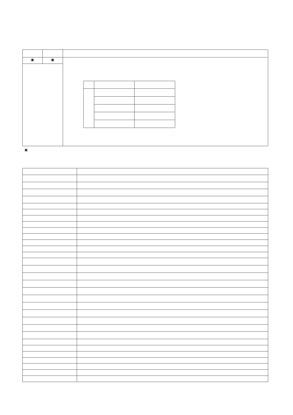
How to know LEDs 1 and 2 alarm display on outdoor unit control board
LED 1 LED 2 Contents of Alarm Display
Alarm display
After LED1 blinks M times, LED2 blinks N times.
This will be repeated.
Number of blinks Type of alarm
N = number of alarm No.
M
2 Alarm P
3 Alarm H
4 Alarm E
5 Alarm F
6 Alarm L
For example: After LED1 blinks twice, LED2 blinks 17 times. This will be repeated.
The alarm shows “P17”.
Alternating
(
: Blink) Connect the outdoor unit maintenance remote controller to the RC plug (3P, BLU) on outdoor unit control board
and make confirmation.
Table 8
Remote control display Alarm contents
E06
Outdoor unit receiving failure from indoor unit
E12
Prohibit starting auto address setting
E15
Auto address alarm (A small number of indoor units)
E16
Auto address alarm (A large number of indoor units)
E20 No indoor unit during auto address setting
E21
E22
Receiving failure of main system from sub system when link wiring is used for outdoor units
Receiving failure of sub system from main system when link wiring is used for outdoor units
E24 Receiving failure of relay control unit from outdoor unit(s)
E25 Failure of outdoor unit address setting (Duplicative)
E26 Inconsistencies in number of outdoor units
E29 Failure of outdoor unit to receive relay control unit
E30 Failure of transferring outdoor unit serial
E31 Wiring error between the P.C. board ( [L-Pow], [HIC] wire)
F04 Compressor 1 discharge temperature sensor abnormal [DISCH1]
F05 Compressor 2 discharge temperature sensor abnormal [DISCH2]
F06 Outdoor unit heat exchanger 1 gas (inlet) temperature sensor abnormal [EXG1]
F07 Outdoor unit heat exchanger 1 liquid (outlet) temperature sensor abnormal [EXL1]
F08 Outdoor temperature sensor abnormal [TO]
F12 Compressor inlet temperature sensor abnormal [SCT]
F14 Supercooling gas temperature sensor abnormal [SCG]
F16 High pressure sensor abnormal, high-load [HPS]
F17 Low pressure sensor abnormal [LPS]
F23 Outdoor unit heat exchanger 2 gas (inlet) temperature sensor abnormal [EXG2]
F24 Outdoor unit heat exchanger 2 liquid (outlet) temperature sensor abnormal [EXL2]
F31 Outdoor unit nonvolatile memory (EEPROM) error
H01 Compressor 1 abnormal current values (Overcurrent)
H03 Compressor 1 CT sensor disconnected, short-circuit
H05 Compressor 1 discharge temperature sensor disconnected
H06 Low pressure abnormal lowering
H07 Oil loss - error
H08 Oil sensor (connection) error 1