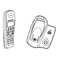
8 TROUBLESHOOTING BY SYMPTOM (BASE UNIT AND
CHARGER UNIT)
If your unit has below symptoms, follow the instructions in remedy column. Remedies depend on whether you have DECT
tester (*1) or not.
Note:
(*1) A general repair is possible even if you don’t have the DECT tester because it is for confirming the levels, such as
Acoustic level in detail.
(*2) Refer to Check Point (Base Unit) (P.23)
8.1. Check Point (Base Unit)
Please follow the items below when BBIC or EEPROM is replaced.
Note:
After the measuring, sock up the solder of TP.
*: PC Setting (P.27) is required beforehand.
The connections of simulator equipments are as shown in Adjustment Standard (Base Unit) (P.28).
Items Adjustment
Point
Procedure Check or
Replace Parts
(A) 2.65V Supply
Confirmation
- 1. Confirm that the voltage between TP187 and GND is 2.65V ± 0.2V. IC2,Q8,C23,
C24,C25,
C26,C27,C38,
R33,R36,
D5,C41,R41,
R42,Q9,
C40,D4,X1,
C32,C33,
C36,C37
(B) 4.0V Supply
Confirmation
- 1. Confirm that the voltage between TP91 and GND is 4.0V ± 0.2V. D4,C40,Q9,
R41,R42,
C41,D5,C75,
C78,C69,
C66,C67,C76,
IC3
(C) VBACK Status
Confirmation
- 1. Confirm that the voltage between J102 and GND is 0V ± 0.4V. IC2,Q8,C23,
C24,C25,
C26,C27,C38,
R33,R36,
D5,C41,R41,
R42,Q9,
C40,D4,R33,
X1,C32,
C33
23
KX-TCD150FXB / KX-TCD150FXC / KX-TCD152FXB / KX-TCA115EXB / KX-TCA115EXC
 Loading...
