Items Adjustment
Point
Procedure Check or
Replace Parts
(K) Sensitivity Receiver
Confirmation
- Follow steps 1 to 3 of (H) above.
4. Set DECT tester power to -88dBm.
5. Confirm that the BER is < 1000ppm.
IC2,IC3,L1,
C43,C78,
C75,C69,C48,
C72,C66,
C67,C76,C57,
C73,L3,
DA1,R66,R67,
C55,C56,
R78,R79,C54,
C58,C86,
R38
(L) Timing Confirmation - Follow steps 1 to 3 of (H) above.
4. Confirm that the Timing accuracy is < ± 2.0ppm.
IC2,IC3,L1,
C43,C78,
C75,C69,C48,
C72,C66,
C67,C76,C57,
C73,L3,
DA1,R66,R67,
C55,C56,
R78,R79,C54,
C58,C86,
R38
(M)* RSSI Level
Confirmation
- Follow steps 1 to 3 of (H) above.
4. Set DECT tester power to -88dBm.
5. Execute the command “readrssi”.
6. Confirm: 25 < returned value < 43 (hex) (0x34 ± F (hex))
IC2,IC3,L1,
C43,C78,
C75,C69,C48,
C72,C66,
C67,C76,C57,
C73,L3,
DA1,R66,R67,
C55,C56,
R78,R79,C54,
C58,C86,
R38
(N)* Receive Audio Check
and Adjustment
ANT
J1
1. Configure the DECT tester (CMD60) as follows;
<Setting>
·
Test mode: FP
·
Mode: Normal
·
PMID: 00000
2. Execute the command “testmode”.
3. Initiate connection from DECT tester.
4. Execute the command “hookoff”.
5. Execute the command “openau”.
6. Connect J1 (Telephone Socket) to Tel-simulator which is connected with 600
Ω.
7. Set line voltage to 48V and line current to 40mA.
8. Connect DECT tester to Tel-simulator.
9. Input audio signal (200mVrms/1kHz tone) to Tel-simulator.
<DECT tester setting>
·
Scramble: On
·
AF Gen. to ADPCM: Off
·
AF Meter Input: ADPCM
·
AF Gen. Frequency: 1000Hz
·
AF Gen. Level: 200mVrms
10. Confirm hearing tone: 300mVrms ± 100mVrms
11. Adjust audio level if required. (Make sure current value using “getmicgain”. And
then execute the command “setmicgain xx”, where xx is the value.)
12. Confirm that the B-field audio distortion with DECT tester is < 5%.
IC2,C21,R31,
C20,C11,
R18,R16,D3,
R12,Q2,
R7,R8,Q3,
R9,R10,
D2,C1,C2,
R77,IC3,
L1,C43,C78,
C75,C69,
C48,C72,C66,
C67,C76,
C57,C73,L3,
DA1,R66,
R67,C55,C56,
R78,R79,
C54,C58,C86,
R38
25
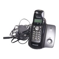
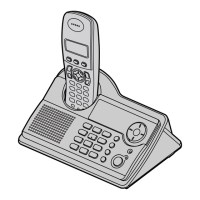
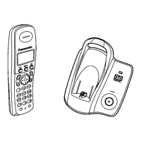
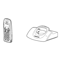
KX-TCD150FXB / KX-TCD150FXC / KX-TCD152FXB / KX-TCA115EXB / KX-TCA115EXC
 Loading...