36
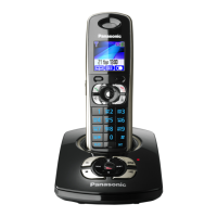
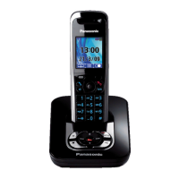
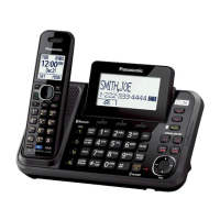
KX-TG8041RU/KX-TGA800RU
9.2. Troubleshooting by Symptom (Base Unit and Charger Unit)
If your unit has below symptoms, follow the instructions in remedy column. Remedies depend on whether you have DECT tester
(*1) or not.
Note:
(*1) A general repair is possible even if you don’t have the DECT tester because it is for confirming the levels, such as Acoustic
level in detail.
(*2) Refer to Check Point (Base Unit) (P.36)
9.2.1. Check Point (Base Unit)
Please follow the items below when BBIC or EEPROM or FLASH is replaced.
Note:
After the measuring, suck up the solder of TP.
*: The Setting Method of JIG (Base Unit) (P.49) is required beforehand.
The connections of simulator equipments are as shown in Adjustment Standard (Base Unit) (P.51).
Items Check
Point
Procedure Check or
Replace Parts
(A) 3.0 V Supply Confirma-
tion
VDD3 1. Confirm that the voltage between test point VDD3 and GND is 3.0 V ± 0.2 V. IC1, C50, C51,
C52, R50, R51,
C53, F1, D1
(B) 1.8 V Supply Confirma-
tion
VDD1 1. Confirm that the voltage between test point VDD1 and GND is 1.8 V ± 0.1 V. Q8, C55, C61,
C64, IC7
(C) Charge Pump
2.5 V Supply Confirma-
tion
VDD5 1. Confirm that the voltage between test point VDD5 and GND is 2.5 V -0.1/+0.3
V.
IC7, C404
(D) Charge Pump
3.0 V Supply Confirma-
tion
VDD4 1. Confirm that the voltage between test point VDD4 and GND is 3.0 V ± 0.2 V. IC7, C422, C425
(E)* BBIC Confirmation - 1. BBIC Confirmation (Execute the command “getchk”).
2. Confirm the returned checksum value.
Connection of checksum value and program number is shown below.
IC7, X1, R76,
R69, R70
(F)* EEPROM Confirmation - 1. EEP-ROM Confirmation (Execute the command “ChkTG7340XXrevYY.bat”).
XX: country code
YY: revision number
2. Confirm the returned checksum value.
3. The checksum is displayed in the last output line.
Note:
“XX”, “YY”, and “checksum” vary depending on the country version. You can find
them in the batch file, PQZZ- mentioned in The Setting Method of JIG (Base
Unit) (P.49).
IC7, RA401,
C401, R405,
IC401
 Loading...