33
2-1-4 Signals and details of I/O connector
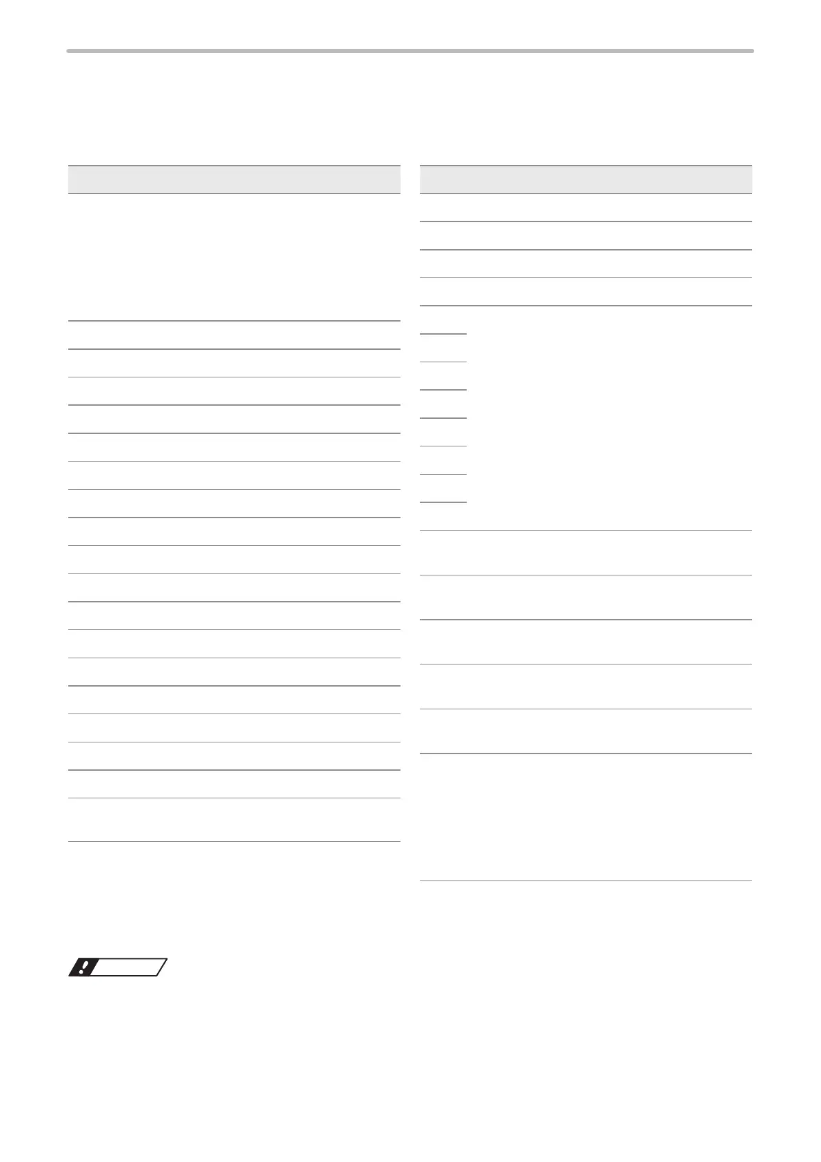
The I/O connector is loaded with the input/output for data setting such as selecting a number and the input/output for the
specic functions.
⿎
Signals in I/O connector
No. Signal name
1 • For NPN models *1
IN COM.
Input common
• For PNP models (-C) *1
OUT COM.
Output common
2 SET IN
3 D0
4 D1
5 D2
6 D3
7 D4
8 D5
9 D6
10 D7
11 D8
12 D9
13 D10
14 D11
15 D12
16 D13
17 D14
18 D15
19 RESERVE
System reservation
No. Signal name
20 SELECT 0 IN
21 SELECT 1 IN
22 SELECT 2 IN
23 TIME HOLD IN
24 RESERVE
System reservation
25
26
27
28
29
30
31
32 CEND 0
Counter 0 end output
33 CEND 1
Counter 1 end output
34 CEND 2
Counter 2 end output
35 CEND 3 / GAP OUT
Counter 3 end output / Date gap output
36 SET OK
Setting completion output
37 • For NPN models *1
OUT COM.
Output common
• For PNP models (-C) *1
IN COM.
Input common
*1 : Signals of No. 1 and No. 37 are different depending on the controller type of NPN or PNP.
• NPN models: LP-4xx(T)U / LP-4xx(T)U-A / LP-4xxS9(T)U / LP-4xxS9(T)U-A / LP-VxxU / LP-VxxU-A / LP-W series
• PNP models (with “-C” in the end of the model name): LP-4xx(T)U-C / LP-4xxS9(T)U-C / LP-VxxU-C
Notice
• Do not invert the power wiring of I/O terminal and I/O connector. It may cause a failure. Common terminals (IN COM. or
OUT COM.) on the I/O connector and the I/O terminal block are connected internally. When IN COM. and OUT COM. in
the I/O terminal are connected to the power supply, it is not necessary to supply the power to IN COM. or OUT COM. in
I/O connector.



 To Next Page