40
2-2 Input/Output Rating
2-2-1 Input rating and input circuit
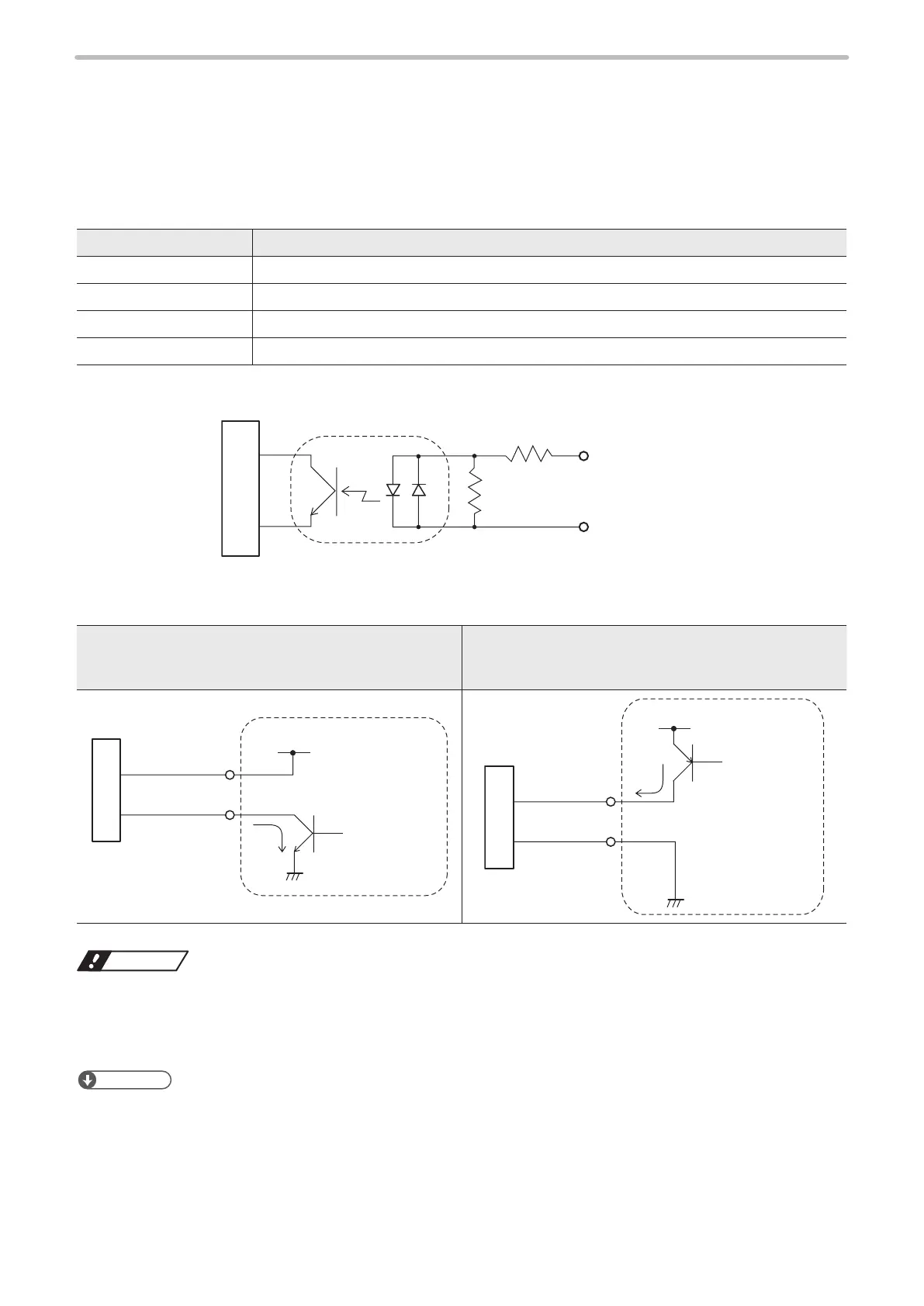
The input rating and input circuit for the I/O terminal and I/O connector are shown as follows:
⿎
Input rating
Item Input on I/O terminal block and I/O connector
Input form Bidirectional photo-coupler (insulated input)
Input ON voltage Difference of voltages between input and input common: 8V or more
Input OFF voltage Difference of voltages between input and input common: 4V or less
Rated input voltage +12V DC to +24V DC
⿎
Input circuit
Input
2kΩ
680Ω
Input common
(IN COM.)
Internal circuit
⿎
Connecting image
For NPN models
[LP-4xx(T)U / LP-4xx(T)U-A / LP-4xxS9(T)U /
LP-4xxS9(T)U-A / LP-VxxU / LP-VxxU-A / LP-W series]
For PNP models
[LP-4xx(T)U-C / LP-4xxS9(T)U-C / LP-VxxU-C]
Input
Input common
(IN COM.)
External power
(+24V DC)
NPN open
collector output
Each input
Input
Input common
(IN COM.)
External power
(+24V DC)
PNP open
collector output
Each input
Notice
• This product has NPN type and PNP type depending on the laser marker models. Make sure the model name and
connect correctly. (PNP type has “-C” in the end of the laser marker model name.)
• Do not short-circuit input common (IN COM.) and output common (OUT COM.). It might cause the failure of the laser
marker.
Reference
• Respective inputs are bidirectional photo-coupler inputs. The regulation for input ON is based on the ON status of photo-
coupler.
• IN COM. terminals on the I/O terminal block and on the I/O connector are the common terminals connected internally.
• Connect the power supply to IN COM. and OUT COM. by using either I/O terminal block or I/O connector.
• DC 2-wire sensor cannot be connected to any input.



 To Next Page