14 DISASSEMBLY INSTRUCTIONS AND ADJUSTMENTS
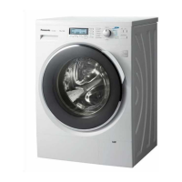
1.Remove the three screws mounting the upper
board.
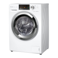
2.Hold and slide the upper board arrow direction
as shown in left figure, and pull it up to remove.
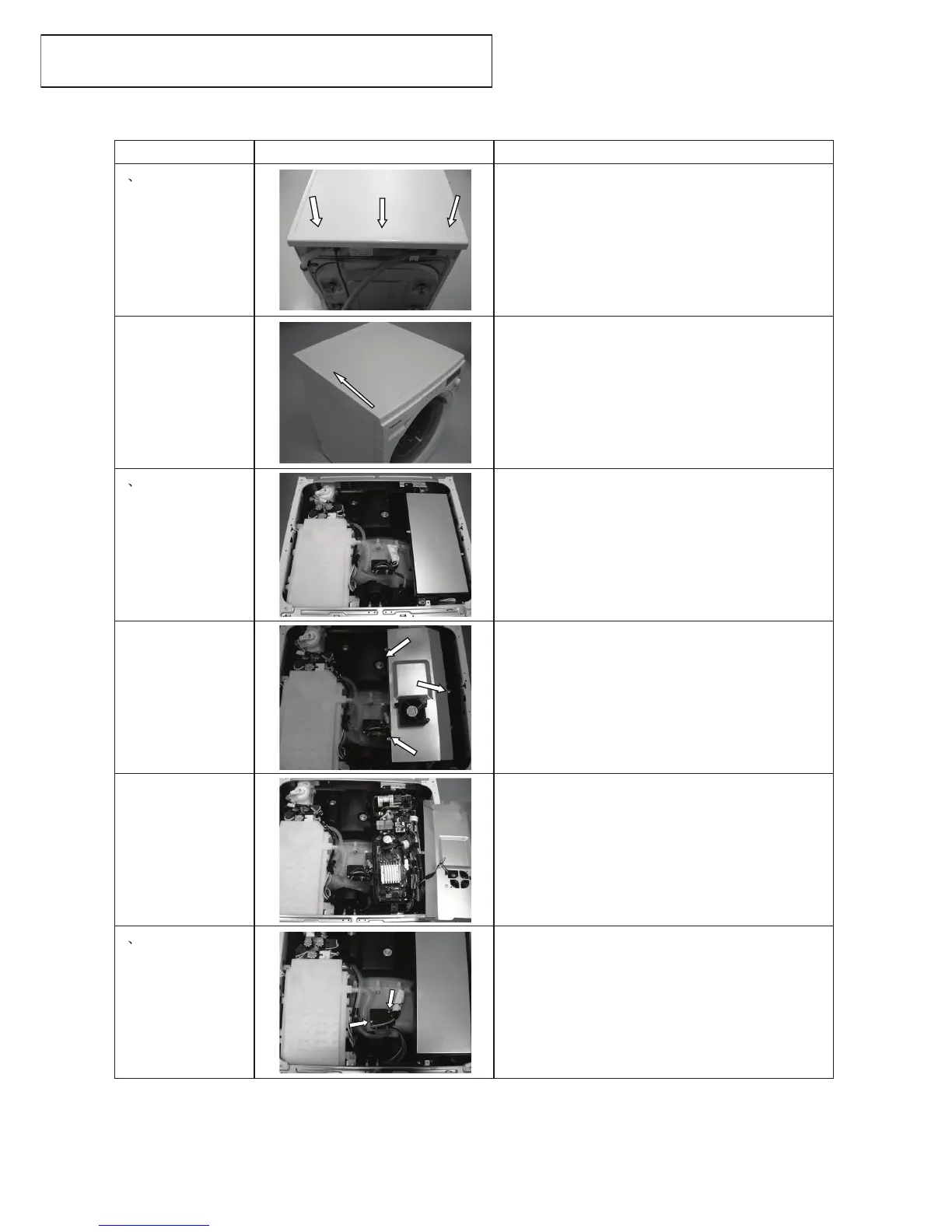
After remove the upper Board,
1.Remove the two screws mounting the PC Board
for power side.
2.Remove the two screws mounting the earth wires
from the PC Board.
3.Up side down the PC Board.
4.Remove the three screws mounting the steel
cover.
5.Remove the one connector of the fan motor and
remove the steel cover.
6.Remove all the connectors and the three lead
wire holders
from the PC Board for power side, and remove
lead wires.
Note:
8-pins red colour connector case may remain,
please note, this connector is not using.
After remove the upper board,
1.Remove the two screws mounting the 3D sensor.
2.Loosen the two lead wire holders, remove tape
and the insulation cover.
-28-
Slide
ProcedureFigure Description
1 Replacement of
the upper board
2 Replacement of
the PC Board
w/components for
Power side
3 Replacement of
the 3D sensor
NA-168VX2/168VG2/148VA2/128VA2/147VB2
 Loading...