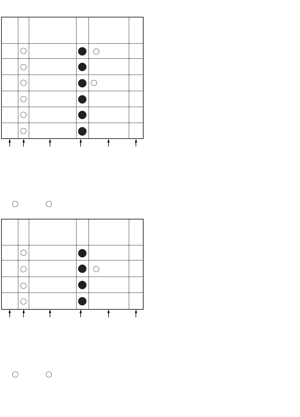
STEP
No.
Ref.
No.
PART REMOVE
NOTE
2
-
-
Lens Ring
Front C.B.A.
1
-
Lens Hood
A B C D E F
3
4
5
6
404 -1
(L-1)
404 -2
83
84
89
82
81
E40
-----
-
Front ESD Angle
2(L-2)
3
404 -3
2
, P6501
-
Infrared Panel
-----
-
Front Case
Section
No.
FRONT CASE PORTION & LAMP PORTION
How to read chart shown above:
A: Order of Procedure steps.
When reassembling, perform steps(s) in reverse order.
B: Ref No.
C: Part to be removed or installed.
D: Section No.
E: Identification of part to be removed, unhooked, unlocked,
released, unplugged, unclamped, or unsoldered.
3
404 404
= 3 Screws , 2(L-1) = 2 Looking Tabs (L-1)
F: Refer to "Notes in chart."
2
2
2
2
2
2
2
STEP
No.
Ref.
No.
PART REMOVE
NOTE
4
9
-
-
Lamp
1
2
3
-
Light Protector
Light Reflector
Lamp Socket Unit
A B C D E F
3(L-3)
281
282
284
283
-----
-----
Section
No.
How to read chart shown above:
A: Order of Procedure steps.
When reassembling, perform steps(s) in reverse order.
B: Ref No.
C: Part to be removed or installed.
D: Section No.
E: Identification of part to be removed, unhooked, unlocked,
released, unplugged, unclamped, or unsoldered.
3
404 404
= 3 Screws , 2(L-1) = 2 Looking Tabs (L-1)
F: Refer to "Notes in chart."
2
2
2
2