Note:
When disassembling or reassembling, make sure that no dust
gets in EVF Unit.
STEP
No.
Ref.
No.
PART REMOVE
NOTE
2
-
12
4 , P001
3(L-1)
Microphone C.B.A.
1
-
Top Operation
C.B.A.
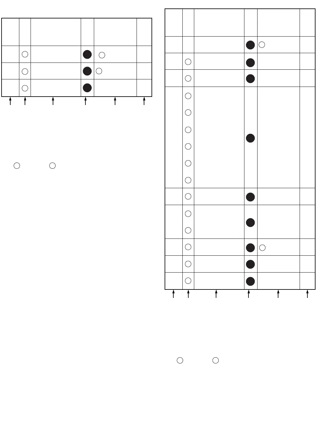
A B C D E F
3
404
E80
E30
50
416
EVF Unit
Section
No.
TOP CASE PORTION & EVF PORTION
How to read chart shown above:
A: Order of Procedure steps.
When reassembling, perform steps(s) in reverse order.
B: Ref No.
C: Part to be removed or installed.
D: Section No.
E: Identification of part to be removed, unhooked, unlocked,
released, unplugged, unclamped, or unsoldered.
3
404 404
= 3 Screws , 2(L-1) = 2 Looking Tabs (L-1)
F: Refer to "Notes in chart."
4
4
4
STEP
No.
Ref.
No.
PART REMOVE
NOTE
2
-
EVF Back Light
C.B.A.
LED Holder
1
-
13
-
Eye Cap
EVF Case Ass’y
A B C D E F
4
5
402
2(L-3), FP952
, FP951
2(L-4)
-----
2(L-5)
40
E50
57
54
60
58
44
LED Diffusion Sheet
-----
LCD Panel
4(L-2)
-
EVF Protect A
-----
-
Protect Plate A
3
6
7
9
(L-6)
56
55
53
59
14
Lens
-----
Lens Holder
14
Eye Sight Lever A
-----
-
EVF Protect B
8
52
-----
14
Eye Sight Lever B
How to read chart shown above:
A: Order of Procedure steps.
When reassembling, perform steps(s) in reverse order.
B: Ref No.
C: Part to be removed or installed.
D: Section No.
E: Identification of part to be removed, unhooked, unlocked,
released, unplugged, unclamped, or unsoldered.
3
404 404
= 3 Screws , 2(L-1) = 2 Looking Tabs (L-1)
F: Refer to "Notes in chart."
Section
No.
4
4
276
-----
Protect Plate B
274
-----
EVF Mask
4
4
4
4
4
4
4
402