Appendices
ENGLISH -
69
Appendix
Mode
Display
resolution *
1
(dots)
Scanning
frequency
Dot clock
frequency
(MHz)
Format
Plug and play *
3
H (kHz) V (Hz)
COMPUTER 1/
COMPUTER 2
HDMI
SXGA 1280 x 1024
63.98 60.0 108.00 R/H - -
76.97 72.0 133.00 R/H - -
79.98 75.0 135.00 R/H o o
1366x768 1366 x 768 47.72 59.8 84.75 R/H - -
SXGA+ 1400 x 1050 65.32 60.0 121.75 R/H - -
WXGA+ 1440 x 900 55.94 59.9 106.50 R/H - -
UXGA 1600 x 1200 75.00 60.0 162.00 R/H o o
WSXGA+ 1680 x 1050 65.29 60.0 146.25 R/H o
*
4
o
*
4
*1: “i” added to the resolution value indicates an interlaced signal.
*2: HDMI signal of 480i and 576i is only supported by 27MHz Dot clock signal.
*3: Where marked "o" signals indicates in Plug and Play is compatible with EDID of projector. Unmarked signals in Plug and
Play may also be compliant if input terminals are written in the format list. Where Plug and Play is unmarked and nothing is
written in the format list, difculties in projecting image may occur even when computer and projector appear to have same
resolution.
*4: For PT-CW330E and PT-CW240E.
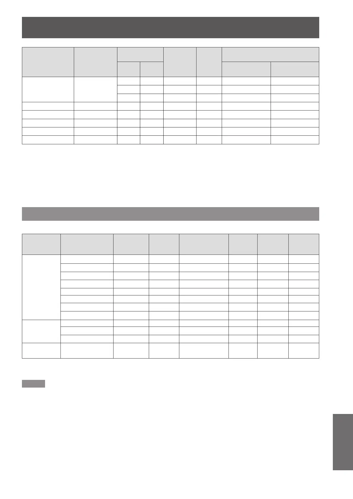
3D compatible signals
3D compatible video signals of this projector are shown in the table below.
Mode 3D signals
Display
resolution *
1
(dots)
Frame
Packing
Side-by-Side (Half)
Top and
Bottom
Frame
sequential
Field
sequential
HDMI
750 (720)/60p 1280 x 720
o - o - -
750 (720)/50p 1280 x 720
o - o - -
1125 (1080)/60i 1920 x 1080i
- o - - -
1125 (1080)/50i 1920 x 1080i
- o - - -
1125 (1080)/24p 1920 x 1080
o - o - -
VGA@120 Hz 640 x 480
- - - o -
SVGA@120 Hz 800 x 600
- - - o -
XGA@120 Hz 1024 x 768
- - - o -
COMPUTER 1/
COMPUTER 2
VGA@120 Hz 640 x 480
- - - o -
SVGA@120 Hz 800 x 600
- - - o -
XGA@120 Hz 1024 x 768
- - - o -
Video/S-Video NTSC --- - - - o o
Video and S-Video support DVD software (HQFS) that is recorded in Field sequential.
*1: “i” added to the resolution value indicates an interlaced signal.
Note
The number of display dots is 1280 x 800 for the PT-CW330E, PT-CW240E and 1024 x 768 for the PT-CX300E.
z
A signal with a different resolution will be projected after converting the resolution to match the projector display.
When interlaced signals are connected, icker may occur on the projected image.
z
Even the above signals exist, some image signals that recorded in special method may not be displayed.
z
The <AUTO ADJ.> operation may not optimize the image position or the resolution, depending on the input signal format or
z
the image contents. In this case, switch to a different image and execute <AUTO ADJ.> again.
 Loading...