1 Safety Precautions 4
1.1. General Guidelines
4
1.2. Leakage Current Check
4
1.3. UV Precaution and UHM Lamp Precautions
4
2 Specifications
5
3 Function for Safety
7
3.1. Interlock Switch
7
4 Serviceman Mode
7
4.1. Setting to Serviceman Mode
7
4.2. Resetting to User Mode
8
4.3. Functions in Serviceman Mode
9
5 Using the Serial Terminals
14
5.1. Examples of Connection
14
5.2. Pin Assignments and Signal Names
14
5.3. Communication Conditions (Factory Setting)
14
5.4. Procedure of Communication Condition Settings
15
5.5. Control commands
15
5.6. Cable specifications
16
6 Using a Wired Remote Control
17
6.1. Connection Example
17
6.2. Setting the Projector ID Number for Remote Control
17
7 Support for Service
19
7.1. Supporting Methods
19
7.2. Note for Replacement of P.C.Boards
19
7.3. Replacement of the lithium battery on the A-P.C.Board
19
8 Cautions for Service
19
8.1. Servicing Methods
19
9 Parts Location
20
9.1. Electrical Parts Location
20
9.2. Electromechanical Parts Location
20
10 Replacement of Lamp Unit
21
10.1. Precautions on Lamp Unit Replacement
21
10.2. Timing of Lamp Unit Replacement
21
10.3. Indication of Lamp Monitor
22
10.4. Procedure of Lamp Unit Replacement
22
11 Disassembly Instructions
25
11.1. Flowchart for Disassembly
25
11.2. Removal of Upper Case
26
11.3. Removal of A-P.C.Board
26
11.4. Removal of J-P.C.Board
27
11.5. Removal of D-P.C.Board
27
11.6. Removal of Power Module
28
11.7. Removal of R-P.C.Board
28
11.8. Removal of S-P.C.Board
28
11.9. Removal of Ballast-1 and Ballast-2 Modules
29
11.10. Removal of Lamp Unit
31
11.11. Removal of Projection Lens
32
11.12. Removal of Analysis Block
32
11.13. Removal of Synthesis Mirror
33
11.14. Removal of Color Wheel Block (Analysis Block)
34
11.15. Removal of Rod (complete)
35
11.16. Removal of Full Ref lection Mirror (complete)
36
11.17. Removal of D MD Block (complete)
37
11.18. Removal of Mechanica l Shutter Unit
38
12 Troubleshooting
39
13 Interconnection Block Diagram
51
13.1. Interconnection Block Diagram (1/2)
51
13.2. Interconnection Block Diagram (2/2)
52
14 Block Diagram
53
14.1. Power Supply
53
14.2. Signal Processing (1/2)
54
14.3. Signal Processing (2/2)
55
14.4. Fan/Motor Drive
56
15 Schematic Diagram
57
15.1. A-P.C.Board (1/11)
58
15.2. A-P.C.Board (2/11)
59
15.3. A-P.C.Board (3/11)
60
15.4. A-P.C.Board (4/11)
61
15.5. A-P.C.Board (5/11)
62
15.6. A-P.C.Board (6/11)
63
15.7. A-P.C.Board (7/11)
64
15.8. A-P.C.Board (8/11)
65
15.9. A-P.C.Board (9/11)
66
15.10. A-P.C.Board (10/11)
67
15.11. A-P.C.Board (11/11)
68
15.12 . CW /D /R/S-P.C .Board
69
15.13. J-P.C.Board
70
16 Circuit Boards
71
16.1. A-P.C.Board (Foil Side)
71
16.2. A-P.C.Board (Component Side)
72
16.3. J-P.C.Board
73
17 Terminal guide of ICs and transistors
75
18 Exploded Views
76
19 Replacement Parts List
80
CONTENTS
Page Page
3
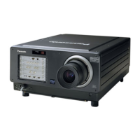
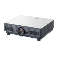
PT-D5600U / PT-D5600E / PT-D5600UL / PT-D5600EL / PT-DW5000U / PT-DW5000E / PT-DW5000UL / PT-DW5000EL
 Loading...