Chapter 1 Preparation — About your projector
30 - ENGLISH
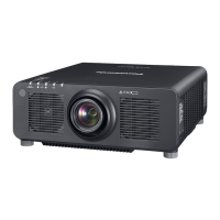
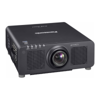
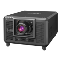
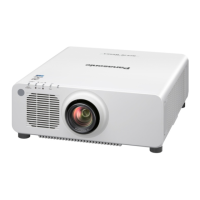
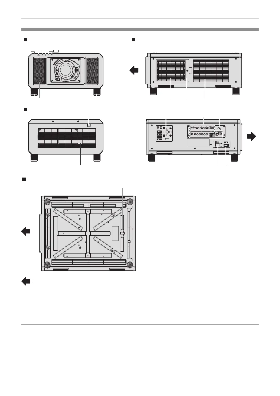
Projector body
1 2 3
4
5 6
7 7
9
8
88 12
16 17
13 14
10
15
Front
Side
Rear
11
Projection direction
Bottom
1 Remote control signal receiver (front)
2 Power indicator <ON (G)/STANDBY (R)>
Indicates the status of the power.
3 Light source indicator <LIGHT1>
Indicates the status of light source 1.
4 Light source indicator <LIGHT2>
Indicates the status of light source 2.
5 Temperature indicator <TEMP>
Indicates the internal temperature status.
6 Filter indicator <FILTER>
Indicates the status of the air lter unit.
7 Adjustable feet
Adjusts the projection angle.
8 Air intake port
9 Remote control signal receiver (rear)
10 Air exhaust port
11 Burglar hook port
Attaches a burglar prevention cable, etc.
12 Air lter cover
The air lter unit is inside.
13 Control panel (x page 31)
14 Connecting terminals (x page 32)
15 Security slot
This security slot is compatible with the Kensington security
cables.
16 <AC IN> terminal
Connect the supplied power cord.
17 <MAIN POWER> switch
Turns on/off the main power.
Attention
f Do not block the ventilation ports (intake and exhaust) of the projector.

 Loading...