16
3-10. Installing the Drain Pipe
● Prepare standard PVC pipe for the drain and connect it to
the indoor unit drain pipe with the supplied hose clamps to
prevent water leaks.
(1) Drain hose connection
● The drain hose is connected below the refrigerant tubing.
(2) Installing the drain hose
● To install the drain hose, first place 1 of the 2 hose bands
over the unit drain port and the other hose band over the
hard PVC pipe (not supplied). Then connect both ends of the
supplied drain hose.
● On the unit drain side, grasp the hose band with pliers and
insert the drain hose all the way to the base.
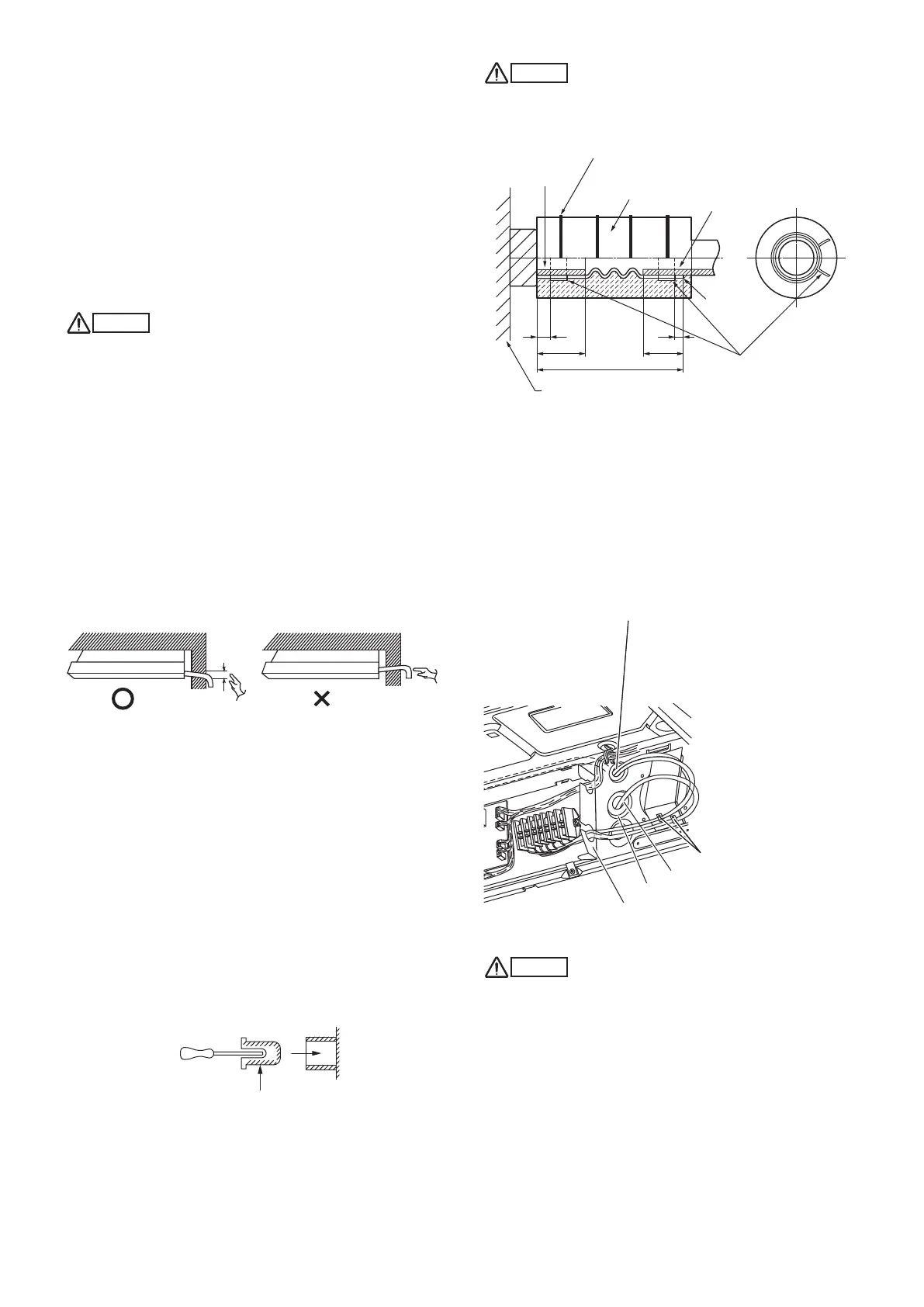
CAUTION
● Attach so that the hose band fastener is on the side of
the drain port. (Fig. 3-33)
● Attach the hose bands so that each is approximately
5 to 25 mm from the end of the supplied drain hose.
● If other commercially available hose bands are used, the
drain hose may become pinched or wrinkled and there
is danger of water leakage. Therefore be sure to use the
supplied hose bands. When sliding the hose bands, be
careful to avoid scratching the drain hose.
● Do not use adhesive tape when connecting the supplied
drain hose to the drain port (either on the main unit or the
PVC pipe).
● Wrap the hose with the supplied drain hose insulation and
use the 4 twist ties so that the hose is insulated with no
gaps.
● Connect the drain pipe so that it slopes downward from the
unit to the outside. (Fig. 3-32)
Good
Not good
Min.
1/100
Fig. 3-32
● Never allow water traps to occur in the course of the piping.
● Insulate any piping inside the room to prevent dripping.
● After the drain piping, pour water into the drain pan to check
that the water drains smoothly.
● If the drain hose is to be raised, use the optional drain up kit.
The drain hose can be raised 60 cm above the top of the
main unit. (For details, refer to the manual for the optional
part.)
* If the drain hose is routed through the left side, refer to Fig.
3-30, and follow the procedure above to install the hose.
Reattach the rubber stopper removed earlier onto the right
side.
The rubber stopper can be inserted easily by using a
screwdriver or similar tool to press the stopper into the drain
port on the main unit. Press the stopper into the main unit
drain port as far as it will go.
Rubber stopper
Screwdriver
Drain port
CAUTION
Check local electrical codes and regulations before wiring.
Also, check any specified instruction or limitations.
140
25 25
5
5
Twist tie
(4 ties)
Unit drain pan
Hose band
(2 bands, supplied)
Drain hose
(supplied)
Position to
fasten hose
bands
Hard PVC pipe
(equivalent to
O.D. 25 mm)
(Field supply)
Drain hose
insulation
(supplied)
Unit drain port
Unit: mm
Fig. 3-33
How to carry out power supply wiring
(1) Wiring connection ports
The power inlet ports are located at the rear and top.
The remote controller wiring inlet ports are located at the rear
and top (for use with the wired remote controller). For details,
refer to Fig. 3-29. For the method used to insert the wiring, refer
to Fig. 3-34.
Attach the supplied eyelet to the power wiring inlet port with
adhesive material (field supply). (Refer to Fig. 3-34)
Fig. 3-34
CAUTION
When removing the fastening bracket from the cover of the
electrical component box, use caution to avoid dropping
the bracket.
(2) How to carry out wiring
● Open the knock-out hole on the rear or top of the main unit.
Attach the supplied rubber grommet and pull the power
wiring into the main unit.
● Feed the wiring into the wiring inlet port on the electrical
component box. Connect the wiring to the terminal plate and
fasten in place with the supplied clamp.
● Perform electrical and grounding work in accordance with
the package A/C power specifications, and following local
electrical codes and regulations.
Power wiring
Supplied eyelet
Remote controller wiring and inter-unit
control wiring inlet port
*
Insert the remote controller wiring and
inter-unit control wiring into the electrical
component box from the inlet port as
shown in the figure. This is done regardless
of whether the wiring was inserted from the
top, rear, or left side of the main unit.
Clamp
Power, inter-unit wiring, remote
controller wiring inlet port
Panaindoor336013Eng.indb16Panaindoor336013Eng.indb16 2012/03/2121:07:072012/03/2121:07:07
 Loading...


