(All schematic diagrams may be modified at any time with the
development of the new technology)
Note:
S401 : Power switch
S402 : < I/P Select switch
S403 : I/P Select > switch
S404 : Enter switch
S406 : Menu/-Setup switch
S407 : Tune_down switch
S408 : Tune_up switch
·
The voltage value and waveforms are the reference voltage
of this unit measured by DC electronic voltmeter (high
impedance) and oscilloscope on the basis of chassis.
Accordingly, there may arise some error in voltage values
and waveforms depending upon the internal impedance of
the tester or the measuring unit.
·
Importance safety notice :
Components identified by
mark have special
characteristics important for safety. Furthermore, special
parts which have purposes of fire-retardant (resistors), high-
quality sound (capacitors), low-noise (resistors), etc. are
used. When replacing any of components, be sure to use
only manufacturer´s specified parts shown in the parts list.
Caution !
IC, LSI and VLSI are sensitive to static electricity.
Secondary trouble can be prevented by taking care during
repair.
·
C over the parts boxes made of plastics with aluminium foil.
·
P ut a conductive mat on the work table.
·
Ground the soldering iron.
·
Do not touch the pins of IC, LSI or VLSI with fingers directly.
13 Schematic Diagram
13.1. Notes of Schematic Diagram
37
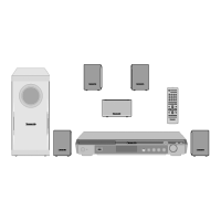
SA-HT40EE
 Loading...