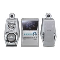
[Standard value : 16 ± 3mV]
Fig. 6
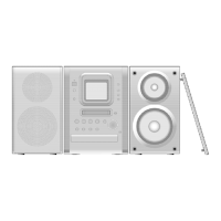
9.1.4. Bias Frequency Check
1. Connect the measuring instrument as shown in Fig. 7.
2. Set the unit to “AUX” position.
3. Insert the normal blank tape (QZZCRA) and set the unit to “REC”
mode (use “ REC/STOP” key).
4. Measure and make sure that the output is within the standard
value.
[Standard value : 98 ± 8kHz]
Fig. 7
9.2. Tuner Section
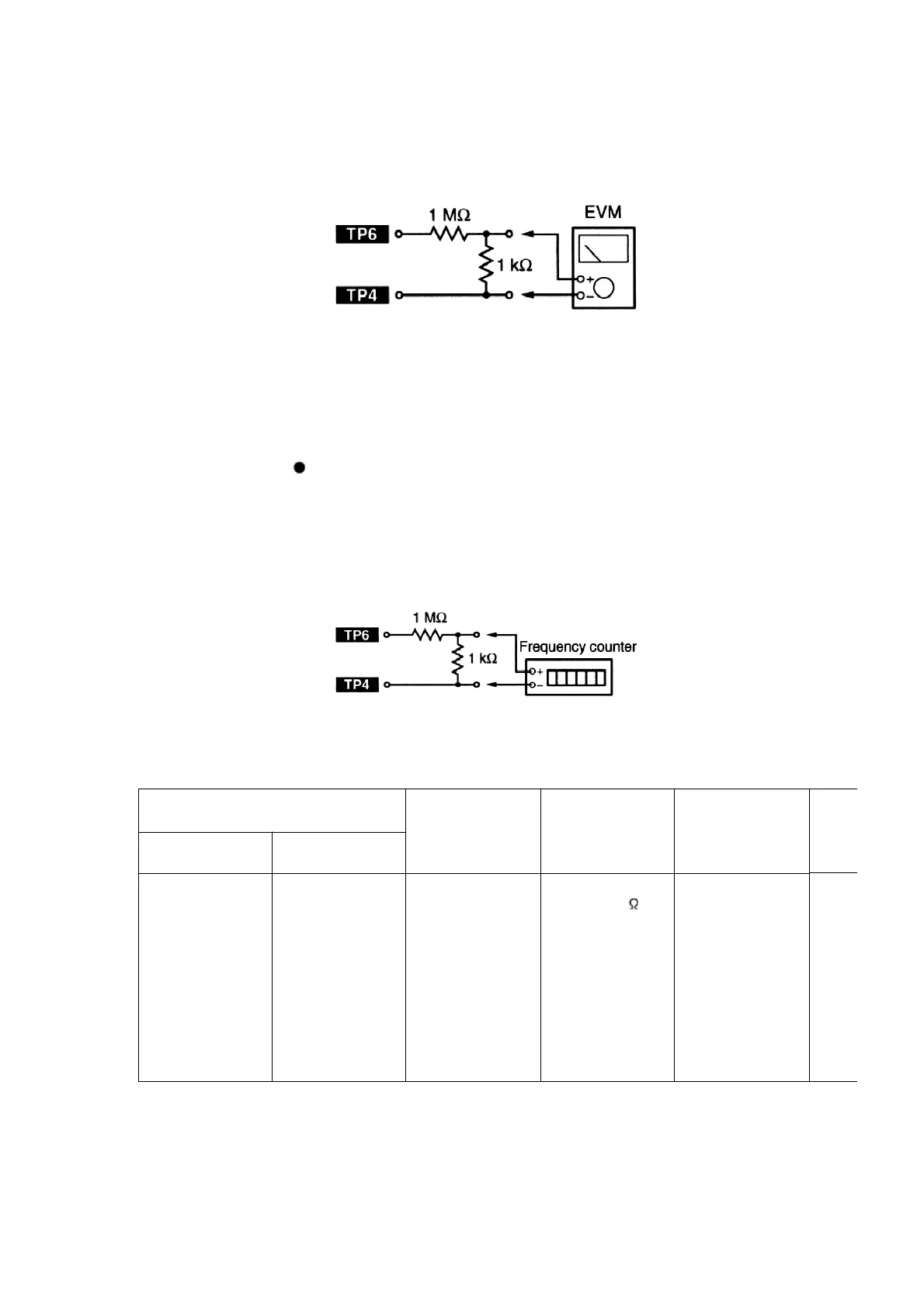
9.2.1. AM-IF Alignment
SIGNAL GENERATOR or SWEEP
GENERATOR
RADIO DIAL
SETTING
INDICATOR
(ELECTRONIC
VOLTMETER or
OSCILLOSCOPE)
ADJUSTMENT
(Shown in Fig. 3)
CONNECTIONS FREQUENCY
Fashion a loop
of several turns
of wire and
radiate a signal
into the loop ant.
of receiver.
450kHz 30%
Mod. at 400Hz
Point of non-
interference. (on
about 600kHz)
Headphones
Jack (32 )
(Fabricate the
plug as shown
in Fig. 2 and
then connect the
lead wires of the
plug to the
measuring
instrument.)
Z102 (AM IFT)
9.2.2. AM-RF Alignment
34