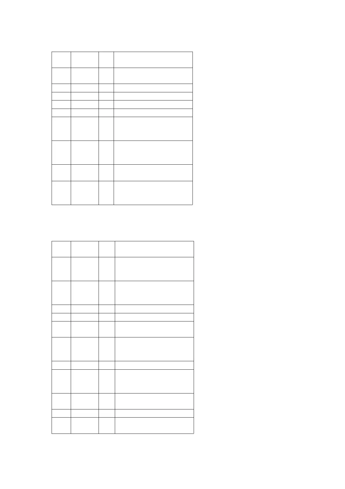
Pin
No.
Mark I/O Function
37 VREF O Reference voltage output
terminal
38 RF1 I RF1 signal input terminal
39 RF2 I RF2 signal input terminal
40 F1 I F1 signal input terminal
41 F2 I F2 signal input terminal
42 CLPF1 — APP compensation LPF
capacitor connection
terminal
43 CLPF2 — RF equalizer adjustment
resistor connection
terminal
44
~47
A
~D
I Beam A~D signal input
terminal
48 CENVC — Beam E signal detection
capacitor connection
terminal
11.2. IC2 (AN8814SB-E1) : FOCUS/TRACKING COIL, SPINDLE/
TRAVERSE MOTOR DRIVE
Pin
No.
Mark I/O Function
1 REG B — 3.3V external transistor
control terminal (Not used,
open)
2 REG M — 3.3V regular output monitor
terminal (Not used,
connected to GND)
3 N.C. — Not used, open
4 OPO O Op-amp output terminal
5 OP- O Op-amp invert output
terminal
6 OP+ O Op-amp non-invert output
terminal (Not used,
connected to GND)
7 Vcc I Power supply terminal
8 1/2
PVcc2
O 1/2 PVcc output terminal 1
(Connected to GND
through capacitor)
9 PVcc2 I Power supply terminal for
driver
10 PGND2 — GND terminal
11 VO4- O Tracking coil driver output
terminal
42