Precautions
RQT9834
11
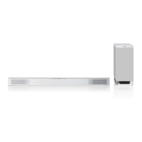
Place the main unit in the desired position and attach each cord onto the
rack or table.
≥ Make sure that the slack of the cord is minimal.
Supplied components
Commercially available components (not supplied)
≥Screws for wall mounting................................................................................................................... k 4
≥Fall prevention cord........................................................................................................................... k 2
≥Screw eyes (to attach the fall prevention cord) ................................................................................. k 2
≥ Use commercially available screws with a nominal diameter of 4.0 mm, which are suitable to the material of the wall (e.g., wood,
steel, concrete, etc.) and are capable of supporting over 33 kg.
≥ Use a cord that is capable of supporting over 33 kg (with a diameter of about 1.5 mm).
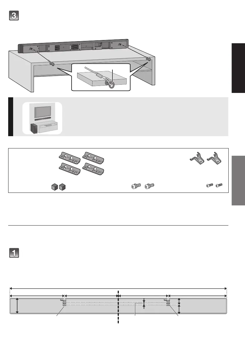
Locate the screwing positions on the wall.
≥ Use the measurements indicated below to identify the screwing positions on the wall.
≥ Position the main unit with at least 50 mm of space above it. If not, it may not be possible to access the buttons.
≥ The position on the wall where the screw is to be attached as well as the screw should be capable of supporting over 33 kg.
≥ Be sure to use a spirit level to ensure that both screwing positions are horizontal to each other.
G Screw eye
≥ Attach at a position capable of
supporting over 33 kg.
≥ Depending on the placement of
the main unit, the screwing
position of the screw eye may
differ.
When attaching the main unit to a wall
∏ 4 Safety holders ∏ 2 Wall mount brackets
∏ 2 Rear pads ∏ 2 Screws with
washer
∏ 2 Screws without
washer
A Wall mount bracket (supplied)
252 mm257 mm 233.5 mm 275.5 mm
1018 mm
75 mm
31.5 mm
43.5 mm
12.5 mm
A A
SC-HTB527EGEB_RQT9834-B.book 11 ページ 2012年12月10日 月曜日 午前11時29分
 Loading...