English
20
●
The computer shown in the illustration is for example
purposes only.
●
Additional computer, cables and conversion adapter
shown are not supplied with this set.
●
Do not set the horizontal and vertical scanning
frequencies for PC signals which are above or below
the specified frequency range.
●
Component Input is possible with the pin 1, 2, 3 of the
Mini D-sub 15P Connector.
●
Change the [Component/RGB-in select] setting in
the [Signal] menu to [Component] (when Component
signal connection) or [RGB] (when RGB signal
connection). (see page 43)
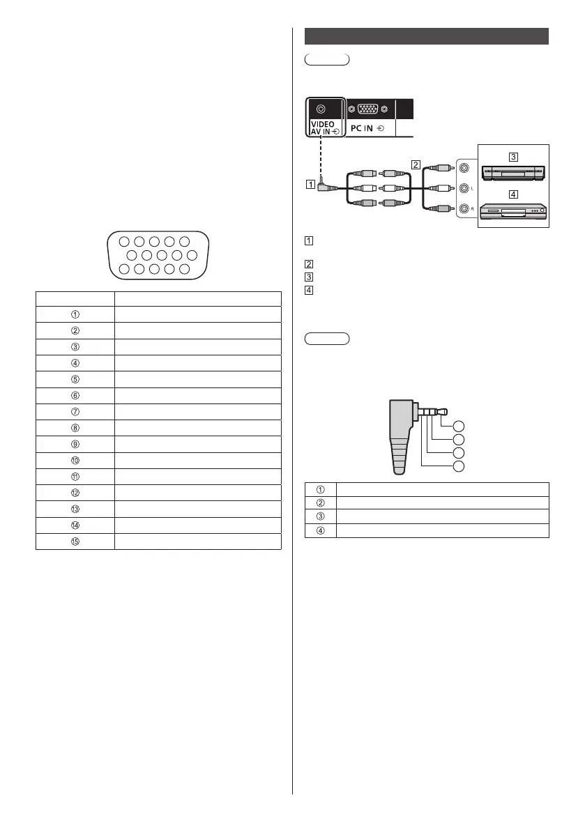
Pin assignments and signal names for PC Input
Terminal (Mini D-sub 15P)
1
678
3
9
45
10
15 14 13 12 11
2
Pin No. Signal Name
R (PR/CR)
G (Y)
B (PB/CB)
NC (not connected)
GND (Ground)
GND (Ground)
GND (Ground)
GND (Ground)
+5 V DC
GND (Ground)
NC (not connected)
SDA
HD/SYNC
VD
SCL
VIDEO terminal connection
Note
●
Video equipment, connection cables and conversion
plugs are not supplied with this unit.
Yellow
White
Red
4-pole mini plug conversion cable (commercially
available)
Audio video pin cable (commercially available)
Video Cassette Recorder
DVD Player
Wiring specifications for 4-pole mini plug
Note
●
Use a 4-pole mini plug (M3) with the following wiring
specifications for the VIDEO terminal of this unit. If
the wiring of a plug is different, audio and video are
not correctly input.
1
3
4
2
Audio L (White)
Video (Yellow)
GND (Ground)
Audio R (Red)