30
9.1.3. White balance adjustment
The adjusting method is different according to the PEAKS EEPROM version.
[copy adjustment] : Peaks EEPROM ver.1.00-
[Differential and copy adjustment] : Peaks EEPROM ver.1.01-
Name of measuring instrument Connection Remarks
W/ B pattern
Color analyzer
(Minolta CA-100 or equivalent)
Panel surface
Steps Remarks
[copy adjustment]
Connect IIC cable (bus controller-cable) after banner OSD appear.
And after SRQ-L, begin an adjustment 2 seconds later.
• Make sure the front panel to be used on the final set is fitted.
• Make sure a color signal is not being shown before adjustment.
• Put the color analyzer where there is little colour variation.
Note:
Copy Adjustment method in service mode.
When you push [OK] key in each item,
Adjustment data is copied between HD data and SD data.
Picture menu : Dynamic
ASPECT : 16:9
Condition is same at
alternative method too.
1. Enter the service mode.
Please receive the Aanalog-RF.
Or, please select CVBS/YUV/HDMI. (No inputting is possible.).
(Forbid Analog-RF with no signal.)
2. A number key [1] or [2] are operated and [WB-ADJ] is displayed.
Check that the color temp is [COOL].
3. A number key [0] is operated and select [METHOD 01].
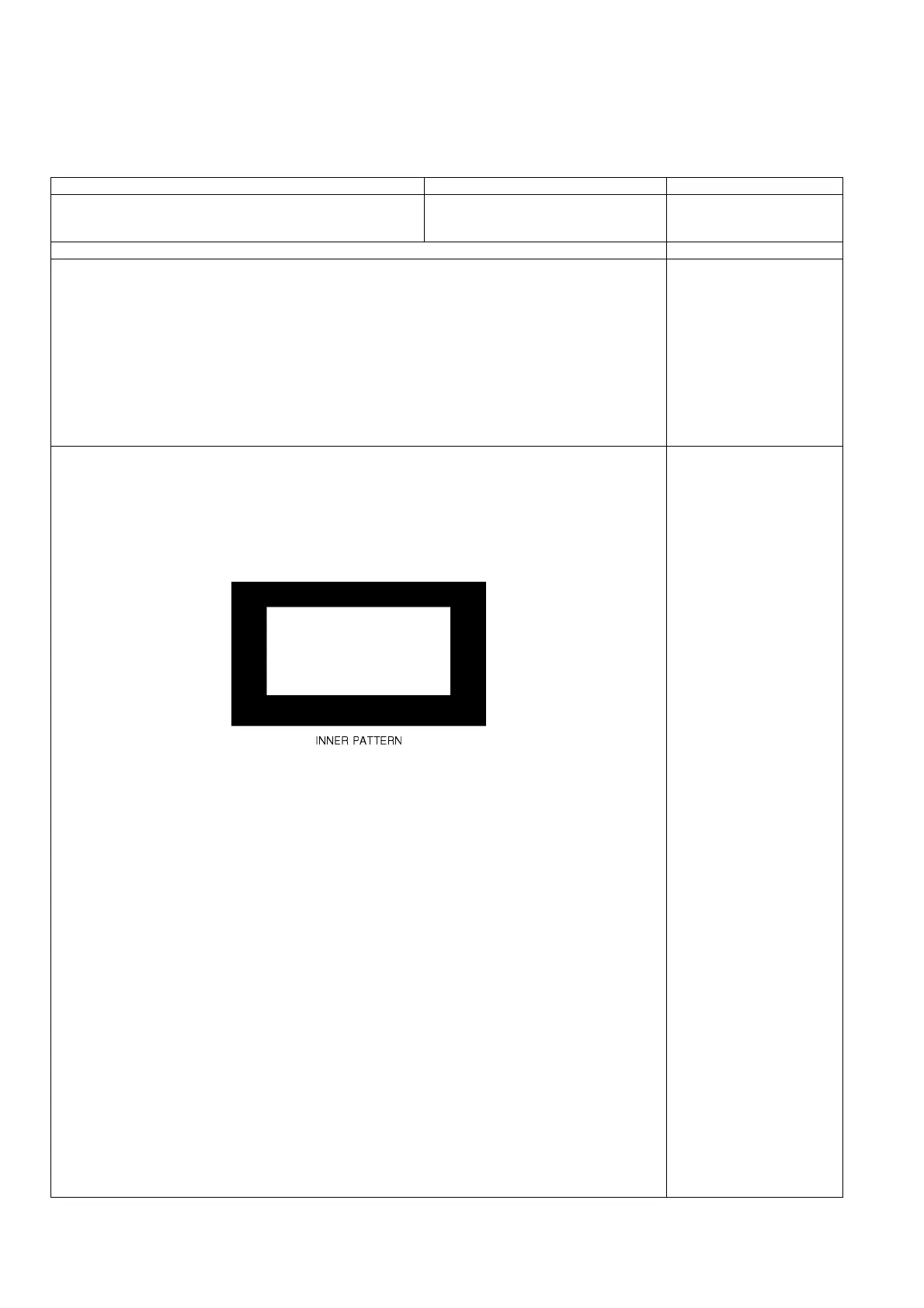
4. A number key [5] is operated and [INNER PATTERN] is displayed.
5. Select [G-CUTOFF] item, using the number-key [3] or [4], and set to [80], using the volume-key [+] or [-].
Also, [B-CUTOFF] and [R-CUTOFF] set to [80].
6. Set [G-DRIVE] at [D0].
7. Touch the signal receiver of color analyzer to the INNER PATTERN center, and adjust B drive and R drive
so x, y become the [COLOR TEMP COOL] in the below table1.
8. All RGB drive increase so that the maximum drive value of RGB may become [FF].
([ALL-DRIVE] set to [FF].)
9. Set color temp to [NORMAL] using [7] key.
10. Fix G-CUTOFF, B-CUTOFF and R-CUTOFF at [80].
11. Set [G-DRIVE] at [D0].
12. Adjust B-DRIVE and R-DRIVE so the INNER PATTERN x, y become the [COLOR TEMP NORMAL] in the
below table1.
13. All RGB drive increase so that the maximum drive value of RGB may become [FF].
([ALL-DRIVE] set to [FF].)
14. Set color temp to [WARM] using [7] key.
15. Fix G-CUTOFF, B-CUTOFF and R-CUTOFF at [80].
16. Set [G-DRIVE] at [D0].
17. Adjust B-DRIVE and R-DRIVE so the INNER PATTERN x, y become the [COLOR TEMP WARM] in the
below table1.
18. All RGB drive increase so that the maximum drive value of RGB may become [FF].
([ALL-DRIVE] set to [FF].)
19. Confirm [METHOD=01].
Please refer table2-3 to address.
Asking matter to execute white balance difference adjustment.
Please feed back the DAC value in the adjusted each color temperature in an internal pattern.
METHOD=01
copy adjustments