32
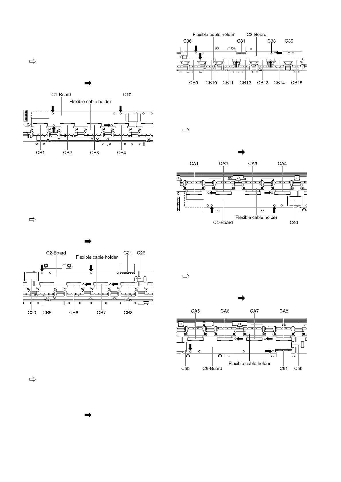
9.19. Remove the C1-Board
1. Remove the Cabinet mount metal bottom (See section
9.17.).
2. Remove the flexible cable holder fastening screws (×5
).
3. Disconnect the flexible cables (CB1, CB2, CB3 and CB4).
4. Disconnect the flexible cable (C10).
5. Remove the screws (×4 ) and remove the C1-Board.
9.20. Remove the C2-Board
1. Remove the Woofer. (See section 9.9.)
2. Remove the Hanger metal R and the One leg bracket.
(See section 9.16.)
3. Remove the Cabinet mount metal bottom (See section
9.17.).
4. Remove the flexible cable holder fastening screws (×5
).
5. Disconnect the flexible cables (CB5, CB6, CB7 and CB8).
6. Disconnect the flexible cables (C20, C21 and C26).
7. Remove the screws (×4 ) and remove the C2-Board.
9.21. Remove the C3-Board
1. Remove the Tuner unit. (See section 9.6.)
2. Remove the Hanger metal L and the One leg bracket.
(See section 9.16.)
3. Remove the Cabinet mount metal bottom. (See section
9.17.)
4. Remove the flexible cable holder fastening screws (×8
).
5. Disconnect the flexible cables (CB9, CB10, CB11, CB12,
CB13, CB14 and CB15).
6. Disconnect the flexible cables (C31 and C36).
7. Disconnect the connectors (C33 and C35).
8. Remove the screws (×5 ) and remove the C3-Board.
9.22. Remove the C4-Board
1. Remove the Fan. (See section 9.10.)
2. Remove the Cabinet mount metal top. (See section 9.17.)
3. Remove the flexible cable holder fastening screws (×6
).
4. Disconnect the flexible cables (CA1, CA2, CA3 and CA4).
5. Disconnect the flexible cable (C40).
6. Remove the screws (×4 ) and remove the C4-Board.
9.23. Remove the C5-Board
1. Remove the Fan. (See section 9.10.)
2. Remove the Hanger metal L. (See section 9.16.)
3. Remove the Cabinet mount metal top. (See section 9.17.)
4. Disconnect the flexible cable holder fastening screws (×6
).
5. Disconnect the flexible cables (CA5, CA6, CA7 and CA8).
6. Disconnect the flexible cables (C50, C51 and C56).
7. Remove the screws (×4 ) and remove the C5-Board.