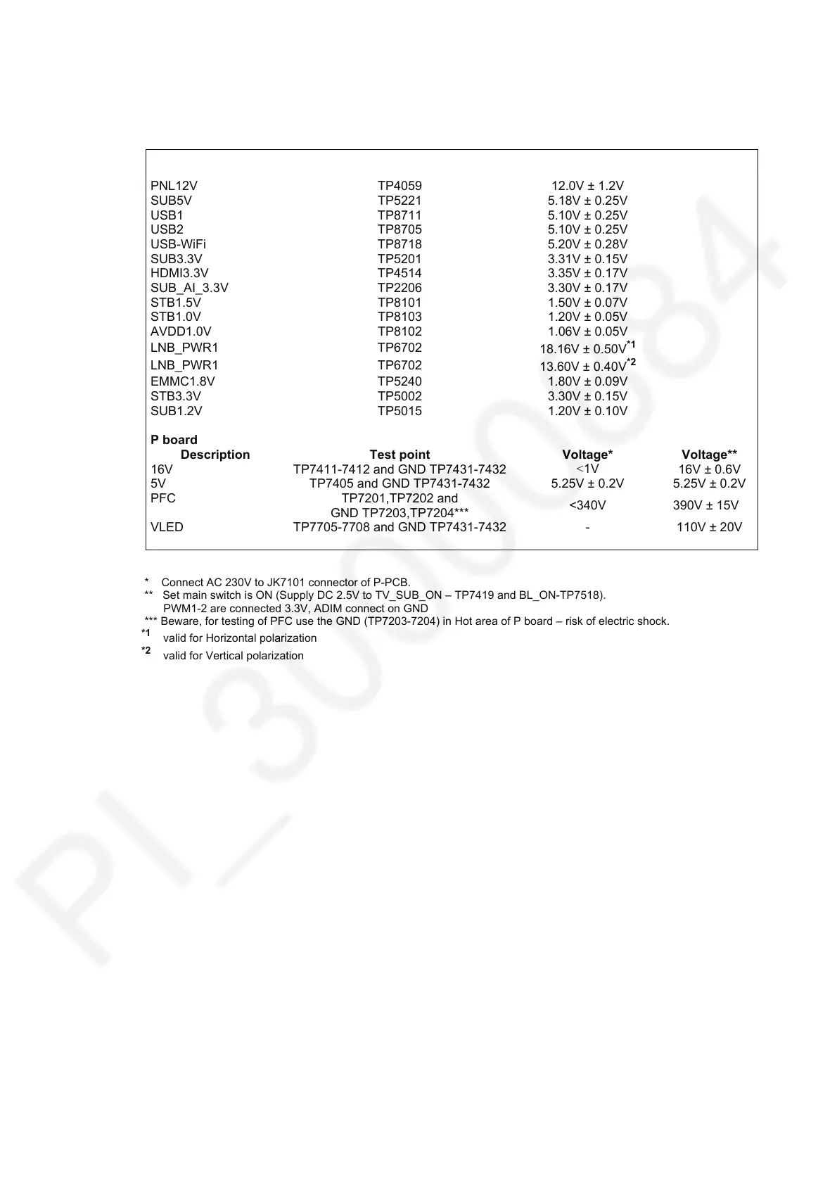
Setting Inspection
Voltage Confirmation
A board
Description Test point
oltage
PNL12V TP4059 12.0V ± 1.2V
SUB5V TP5221 5.18V ± 0.25V
USB1 TP8711 5.10V ± 0.25V
USB2 TP8705 5.10V ± 0.25V
USB-WiFi TP8718 5.20V ± 0.28V
SUB3.3V TP5201 3.31V ± 0.15V
HDMI3.3V TP4514 3.35V ± 0.17V
SUB_AI_3.3V TP2206 3.30V ± 0.17V
STB1.5V TP8101 1.50V ± 0.07V
STB1.0V TP8103 1.20V ± 0.05V
AVDD1.0V TP8102 1.06V ± 0.05V
LNB_PWR1 TP6702
18.16V ± 0.50V
*1
LNB_PWR1 TP6702
13.60V ± 0.40V
*2
EMMC1.8V TP5240 1.80V ± 0.09V
STB3.3V TP5002 3.30V ± 0.15V
SUB1.2V TP5015 1.20V ± 0.10V
P board
Description Test point
oltage*
oltage**
16V
TP7411-7412 and GND TP7431-7432
<1V
16V ± 0.6V
5V TP7405 and GND TP7431-7432 5.25V ± 0.2V 5.25V ± 0.2V
PFC TP7201,TP7202 and
GND TP7203,TP7204***
<340V 390V ± 15V
VLED TP7705-7708 and GND TP7431-7432 - 110V ± 20V
* Connect AC 230V to JK7101 connector of P-PCB.
** Set main switch is ON (Supply DC 2.5V to TV_SUB_ON – TP7419 and BL_ON-TP7518).
PWM1-2 are connected 3.3V, ADIM connect on GND
*** Beware, for testing of PFC use the GND (TP7203-7204) in Hot area of P board – risk of electric shock.
*1
valid for Horizontal polarization
*2
valid for Vertical polarization